I have Sound Lab speakers. For Sound Lab speakers, they use two transformers. One is for high frequency and one is for bass. The high frequency transformer’s low limit is 400 hz. If I use two of same kind of transformers and connect them in parallel, can I extend the low limit? Do you foresee any problems to do this?
Thanks in advance!
Jim
Thanks in advance!
Jim
Last edited:
No, connecting two of the HF transformers in parallel will not extend their low frequency power handling capabilility.
Both transformers would "see" the same input voltage and would limit at the same voltage level as for one transformer.
Can you explain what it is you are trying to do?
Are you wanting to use the transformers in an application other than your SL speakers?
Both transformers would "see" the same input voltage and would limit at the same voltage level as for one transformer.
Can you explain what it is you are trying to do?
Are you wanting to use the transformers in an application other than your SL speakers?
Well, if you wire two HF transformers primaries in parallel and secondaries in series, the output voltage will be doubled. That means you will need half of input voltage to get the same output level. So, compared to a single transformer , you can get the same output level for halved frequency(200 Hz).
Regards,
Lukas.
Regards,
Lukas.
No, connecting two of the HF transformers in parallel will not extend their low frequency power handling capabilility.
Both transformers would "see" the same input voltage and would limit at the same voltage level as for one transformer.
Can you explain what it is you are trying to do?
Are you wanting to use the transformers in an application other than your SL speakers?
I will still use the transformers for SL speakers. Basically, I am trying to eliminated the crossover in signal path because the speakers sound best without any RC network. So, I need to extend the frequency range.
Great! This is exactly what I have in my mind. However, do you foresee any problems because the output voltage is doubled?Well, if you wire two HF transformers primaries in parallel and secondaries in series, the output voltage will be doubled. That means you will need half of input voltage to get the same output level. So, compared to a single transformer , you can get the same output level for halved frequency(200 Hz).
Regards,
Lukas.
Best
Jim
Great! This is exactly what I have in my mind. However, do you foresee any problems because the output voltage is doubled?
Best
Jim
You can only foresee problems if you measure impedance and frequency response.
Mostly to low impedance given the most problems. Most esl user have heavy powerfull amplifiers because the esl/transformer combination have much problems. Most toroid transformer have some extra problems ( more winding capacity, core saturation, core non linearity)
If esl (transformer) is good designed a nice small power tube amplifier will do the job easely.
Last edited:
I will still use the transformers for SL speakers. Basically, I am trying to eliminated the crossover in signal path because the speakers sound best without any RC network. So, I need to extend the frequency range.
If you are keen on removing the RC HP network, probably the best way would be with bi-amping and rolling off the lows reaching the amplifier driving the toroidal with a line level crossover. To avoid core saturation only a first-order filter(-6dB/oct) roll off slope is required so the crossover could be as simple as a single capacitor in line between the preamp and power amp.
... do you foresee any problems because the output voltage is doubled?
Yes, there will be problems if you hook up two of the SL HF toroidal transformers with primaries in parallel and secondaries in series. Since you have doubled your step-up ratio the same output will require only half the input voltage as Bazukaz mentioned. However doubling the step-up ratio results in the impedance being reduced by a factor of 4 in its passband. SL speakers are already a rather difficult load for amplifiers, so this is not a good thing.
The other consequence of putting the secondaries from push-pull designed transformers in series is that the parasitic capacitance between windings will be much greater. This will most likely reduce your upper bandwidth limit to < 20Khz.
Not only would your Impedance be effected by the transformation ratio for the higher frequency's end of the bandwidth, But, Paralleling two primary winding's of two identical transfomer's will also cut your impedance in have for the lower frequency's.
For instance if your properly designed transformer has an Impedance of 4 ohms at 200Hz then it now will be 2 Ohms at 200Hz!
This is because the primary's inductance value of both transformers are added together and the impedance would be the same as paralleling two resistors of the same value, Unless they share the same Mutual Magnetic flux.
If they are sharing the same magnetic flux then the values would still the same as that of a single primary winding. 😉
Inductors in Parallel and Parallel Inductor Circuits
In order to get the effect you want you would have to have 4 transformers with their Primary's in a series parallel configuration.
But, this would also raise your overall transformer self capacitance too!
FWIW
jer 🙂
Last edited:
Hi,
The low frequency limit of the high frequency transformer has
nothing to do with the transformer, everything to do with the x/o.
I don't remotely understand the conjecture involved here.
rgds, sreten.
The low frequency limit of the high frequency transformer has
nothing to do with the transformer, everything to do with the x/o.
I don't remotely understand the conjecture involved here.
rgds, sreten.
The low frequency limit of the high frequency transformer has
nothing to do with the transformer, everything to do with the x/o.
I don't remotely understand the conjecture involved here.
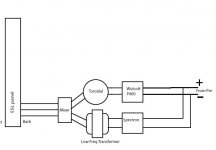
The crossover between the LF and HF transformer in the SL and Acoustat interfaces is defined by the "mixer" resistors and capacitors on the secondary side of the transformers. The RC parts the OP is wanting to remove on the primary side of the HF transformer are only needed to keep the HF transformer core from saturating during high amplitude LF signals. They have minimal impact on the frequency response of the signal reaching the ESL panel since their roll off doesn't start til well below the "mixer" crossover point where the LF transformer has taken over.
The attached schematic shows the Acoustat interface.
Responses can be seen here:
http://www.diyaudio.com/forums/plan...cls-ii-stators-best-way-do-2.html#post3822064
The SL mixer behavior isn't as obvious until you include the high resistance primary of the LF transformer.
An example SL circuit can be seen here:
http://www.diyaudio.com/forums/planars-exotics/254723-acoustat-mk-series-2.html#post3911097
Attachments
Actually, it is bi-amping now. I have tried with a 36 uF capacitor as 1st order filter, but I still prefer the sound without the capacitor.If you are keen on removing the RC HP network, probably the best way would be with bi-amping and rolling off the lows reaching the amplifier driving the toroidal with a line level crossover. To avoid core saturation only a first-order filter(-6dB/oct) roll off slope is required so the crossover could be as simple as a single capacitor in line between the preamp and power amp.
I use Wolcott P400 as high fequency amp and Spectron Musician III as bass amp. I understand the impedance of speaker can be low so I use a 8 ohm DIY wire resistor at treble amp output for safey.Yes, there will be problems if you hook up two of the SL HF toroidal transformers with primaries in parallel and secondaries in series. Since you have doubled your step-up ratio the same output will require only half the input voltage as Bazukaz mentioned. However doubling the step-up ratio results in the impedance being reduced by a factor of 4 in its passband. SL speakers are already a rather difficult load for amplifiers, so this is not a good thing.
Adding a serie resistor is a good idea to protect your amplifier but not a good idea to controle your transformer.
Actually, it is bi-amping now. I have tried with a 36 uF capacitor as 1st order filter, but I still prefer the sound without the capacitor.
I use Wolcott P400 as high fequency amp and Spectron Musician III as bass amp. I understand the impedance of speaker can be low so I use a 8 ohm DIY wire resistor at treble amp output for safey.
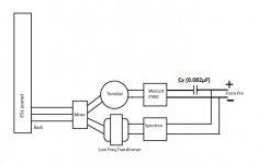
From the size of the capacitor you mention, I am assuming you are putting the capacitor in series between the Wolcott P400 and the HF transformer. What I was suggesting was to connect the amplifier directly to the transformer and perform the HP filtering between the preamp and amp. The P400 specifications list input impedance of 100K, so a 0.082uF series capacitor should do the filtering you desire. See Attachment #1.Actually, it is bi-amping now. I have tried with a 36 uF capacitor as 1st order filter, but I still prefer the sound without the capacitor.
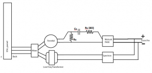
Are you saying that you are putting an 8ohm resistor in series between the P400 and the HF transformer like "Rs" in Attachment #2? If so I would agree with the comment by esltransformer above. Such a high value series resistance would result in rolling off the top octave(20kHz down by -6dB to -9dB). It would also increase the magnitude of core related distortion artifacts induced in the secondary.I use Wolcott P400 as high fequency amp and Spectron Musician III as bass amp. I understand the impedance of speaker can be low so I use a 8 ohm DIY wire resistor at treble amp output for safey.
Looking again at Attachment #2, are you leaving "Rx" in place shunting the transformer primary?
Or are you removing it along with "Cx" when doing your comparisons.
Have you also removed the SL brilliance control from your circuit?
Attachments
Last edited:
From the size of the capacitor you mention, I am assuming you are putting the capacitor in series between the Wolcott P400 and the HF transformer. What I was suggesting was to connect the amplifier directly to the transformer and perform the HP filtering between the preamp and amp. The P400 specifications list input impedance of 100K, so a 0.082uF series capacitor should do the filtering you desire. See Attachment #1.
This is very interesting idea. I will definitely try it. I used to use an active crossover where the capacitor is. But I can’t hear too much of difference between a capacitor and active crossover.
Are you saying that you are putting an 8ohm resistor in series between the P400 and the HF transformer like "Rs" in Attachment #2? If so I would agree with the comment by esltransformer above. Such a high value series resistance would result in rolling off the top octave(20kHz down by -6dB to -9dB). It would also increase the magnitude of core related distortion artifacts induced in the secondary.
Looking again at Attachment #2, are you leaving "Rx" in place shunting the transformer primary?
Or are you removing it along with "Cx" when doing your comparisons.
Have you also removed the SL brilliance control from your circuit?
No. I put a resistor where the Rx is. I don’t use Rs and Cx.
Yes. I removed the SL brilliance control and don’t use it.
Best
Jim
- Status
- Not open for further replies.
- Home
- Loudspeakers
- Planars & Exotics
- Transformer questions