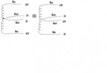
The other winds are
5.2V 0V (Dark Green, Green)
and
16V 0V 16V (Brown, Black Brown)
There was a preamp section in this receiver for the 16V...
5.2V 0V (Dark Green, Green)
and
16V 0V 16V (Brown, Black Brown)
There was a preamp section in this receiver for the 16V...
Oh sorry... of course you cut all the wires! If you look at your first photo, it is pretty clear how the wires are paired.
Remeber the center tap is formed by the start of one winding and the finish of the other...
Just keep track of them. What you want is 2 coils each producing your target voltage.
Don't do the the virtual ground thing unless you're forced to...
Send a PM if you please!
Remeber the center tap is formed by the start of one winding and the finish of the other...
Just keep track of them. What you want is 2 coils each producing your target voltage.
Don't do the the virtual ground thing unless you're forced to...
Send a PM if you please!
OK....I will make sure the correct black wire pairs with the correct blue one which is on the same winding.
Now instead of unwinding a trannie of double the voltage you need, you could split them at the centertap and get two separate windings of the voltage you want....and have 1/2 the total VA rating on each secondary winding...
Is this correct?
Now instead of unwinding a trannie of double the voltage you need, you could split them at the centertap and get two separate windings of the voltage you want....and have 1/2 the total VA rating on each secondary winding...
Is this correct?
NO... not quite. You have 2 windings there, side by side. These are joined to make 40-0-40.
You could simply parallel the 2 windings to make a high current 40 VAC winding and then the virtual ground technique.
What is you target AC voltage?
You could simply parallel the 2 windings to make a high current 40 VAC winding and then the virtual ground technique.
What is you target AC voltage?
If this is for a 50 watt chip amp you really want about 28-30 VAC... so you're only pulling away about 25% of the winding.
😉
😉
John,
With the gas prices in Utah, I hope that it somehow translates back down to you 🙂 The trickle down effect...you know??? 🙂
Get a good transformer that suits your needs. Here's a good source at a good price.
http://stores.ebay.com/antek-inc
I have bought several and they are good transformers.
If your around SLC.....Backer's Bakery........ Me....
Bearman,
Gas prices in Utah? I MAKE more than 25% of the Gas and Diesel in Utah!! I work for the biggest Petroleum refiner in the valley,
Gas and Diesel prices are finally going down here....but don't get used to it...one hurricane, or North Korean Missle test, or cheap shot from Hugo will make the prices skyrocket again...no tellin where they will end up...
Thise Antec torroids are great, but pricey. I usually buy from Steve at Apexjr.com
Oops... sorry John, disregard post my last post... big error.
20-22 rail voltage is right
Perhaps the best thing to do is to parallel the windings and use a cap stack to make a virtual ground.
Or use the windings seperately and use 4 caps as you have drawn... this will still give you about 28 +/- rails though. That's ok though gives headroom for transients... common sense and the built in temp limit provide the rest.
Are you interested in keeping the 5 and 16 volts windings and are they on top... final layers?
😉
The 5V winding will power the power LED, and the 16V 0V 16V windings, well, I donno. I may just put in a TDA1543 DAC I have (regulated dwn to 12V via LM317)
So the Amp will have Optical Digital input -> DAC -> Stepped Attenuator -> LM3886 Amp-> Speakers....
I think both windings are on top - yes...
So the Amp will have Optical Digital input -> DAC -> Stepped Attenuator -> LM3886 Amp-> Speakers....
I think both windings are on top - yes...
John,
With the gas prices in Utah, I hope that it somehow translates back down to you 🙂 The trickle down effect...you know??? 🙂
Get a good transformer that suits your needs. Here's a good source at a good price.
http://stores.ebay.com/antek-inc
I have bought several and they are good transformers.
If your around SLC.....Backer's Bakery........ Me....
With the gas prices in Utah, I hope that it somehow translates back down to you 🙂 The trickle down effect...you know??? 🙂
Get a good transformer that suits your needs. Here's a good source at a good price.
http://stores.ebay.com/antek-inc
I have bought several and they are good transformers.
If your around SLC.....Backer's Bakery........ Me....
So where's Backer bakery? I am on the North end of Town by the Gateway...
I think I solved my Toroid issue, and will not be buying a new one...I still have one more I may trade if the correct one comes along...
Now instead of having a higher voltage toroid I can't use, I have a correct dual voltage toroid I can use... A little inginuity I guess....Viva la DIYAudio Spirit!!
Good for you John. Power is always a little spooky for me, so I choose not to mess with things too much on that end. ZAP!
South Temple, between 4-5th East, South Side of the street. Been there 60 years.
Here's to DIY.
South Temple, between 4-5th East, South Side of the street. Been there 60 years.
Here's to DIY.
Sorry John,
but they are not.
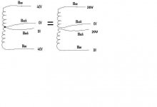
One is a centre tapped 40-0-40 and the other is a twin secondary 0-20, 0-20.
You can join the twin secondaries to give the equivalent centre tapped form, but it will only be a 20-0-20 NOT 40-0-40.
Have another look.
but they are not.
One is a centre tapped 40-0-40 and the other is a twin secondary 0-20, 0-20.
You can join the twin secondaries to give the equivalent centre tapped form, but it will only be a 20-0-20 NOT 40-0-40.
Have another look.
Yes!! This is exactly what I was looking for from the beginning of this post.
Turning a 40V 0V 40V into a 20V 0V 20V toroid I want for a "Special" Gainclone and an Amp5 -
I know I have to join the post-rectified/smoothed pos and neg output to make the new 0v plane...
Turning a 40V 0V 40V into a 20V 0V 20V toroid I want for a "Special" Gainclone and an Amp5 -
I know I have to join the post-rectified/smoothed pos and neg output to make the new 0v plane...
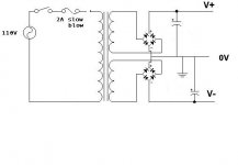
Nope. This is what you will have...
The tie between the two windings just creates a common point (0V). Seperating the two windings does not affect each windings voltage, it just removes the common voltage point.
So, looking closely at the windings, do they appear to be layered over each other? The other low voltage windings may make it difficult, as they are probably right over some of the stuff you want to unwind.
If you go for the virtual ground approach, DO NOT tie the virtual ground to your chassis ground. If you want to know why, keep them seperate and measure the voltage between them...
Attachments
Hi John,
I said
I said
What do you mean by saying what appears contradictoryOne is a centre tapped 40-0-40 and the other is a twin secondary 0-20, 0-20. You can join the twin secondaries to give the equivalent centre tapped form, but it will only be a 20-0-20 NOT 40-0-40.
It cannot be done easily.Turning a 40V 0V 40V into a 20V 0V 20V toroid
Hello Brian..
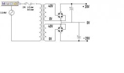
I noticed earlier that you also have been getting these KLH2400 receivers and reusing the toroids...this is one of those toroids and I want to use it as a dual 20V winding tranny or a 40VCT single secondary tranny.... have you read up on this post?
Will this work? Notice I took off the chassis ground...
Attachments
- Status
- Not open for further replies.
- Home
- Amplifiers
- Chip Amps
- Transformer question for Chipamp...