Hi L0rdGwyn,
I have no doubt that Sowter would replace the transformer if it were proven faulty, but you'd probably want to be 100% sure it is before sending it back across the pond.
Do you have a schematic for the build?
Thanks
I have no doubt that Sowter would replace the transformer if it were proven faulty, but you'd probably want to be 100% sure it is before sending it back across the pond.
Do you have a schematic for the build?
Thanks
Another thing you may find helpful, depending on the headphones being used, is to put a 6 ohm resistor in series with a 2 ohm resistor on the 8 ohm output, with the 2 ohm end at ground. This gives you a padded output for hyper sensitive headphones with a far lower noisefloor. This is really helpful for Grados and IEMs.
Something else that might be worth checking
Could the unrectified AC filament supply be coupling with the DC plate supply/signal of your output tubes?
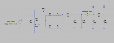
As best as I can tell, you've got rectification, filtering and regulation of the filament supply together on the sides of chassis. They are connected to the heater windings via longish wiring running from the sides to the center of the amp. As I read him, Rod Coleman recommends a different setup: rectify and filter close to the heater windings. From Rod's installation guide:
Maybe try moving the "raw dc" board to the center of the chassis. Might help.
Unrelated questions: Are the larger Solen caps the parafeed output caps? How/where do the parafeed caps connect to the plate and the output transformer? I can't tell from the wiring pic. I'm admiring your layout, but can't see this part of your circuit.
cheers, Derek
Could the unrectified AC filament supply be coupling with the DC plate supply/signal of your output tubes?
As best as I can tell, you've got rectification, filtering and regulation of the filament supply together on the sides of chassis. They are connected to the heater windings via longish wiring running from the sides to the center of the amp. As I read him, Rod Coleman recommends a different setup: rectify and filter close to the heater windings. From Rod's installation guide:
"4.6. Wiring between rectifiers, snubbers, and C1 capacitor: keep these really tight. A 1.2A dc supply runs 6A pulses through these! The pulses will electromagnetically couple into your signal circuits if these are long.
4.7. Transformer to rectifiers: keep shorter than 75mm, same reason as above.
4.8. Raw-DC wiring from rectifiers/capacitors to Regulator's board: you can make these up to 2 metre long, and mount in a different chassis."
4.7. Transformer to rectifiers: keep shorter than 75mm, same reason as above.
4.8. Raw-DC wiring from rectifiers/capacitors to Regulator's board: you can make these up to 2 metre long, and mount in a different chassis."
Maybe try moving the "raw dc" board to the center of the chassis. Might help.
Unrelated questions: Are the larger Solen caps the parafeed output caps? How/where do the parafeed caps connect to the plate and the output transformer? I can't tell from the wiring pic. I'm admiring your layout, but can't see this part of your circuit.
cheers, Derek
Hi L0rdGwyn,
I have no doubt that Sowter would replace the transformer if it were proven faulty, but you'd probably want to be 100% sure it is before sending it back across the pond.
Do you have a schematic for the build?
Thanks
Thanks for the advice. That is the thing, I am not so sure it is faulty, perhaps it was my application that was flawed. It does seem bizarre to me that I would have asymmetrical performance across two identical windings. Regardless, with the cathodes bypassed on the output, the most sinister of the 60Hz noise is gone and the rest is inaudible, so I think I can sleep soundly tonight.
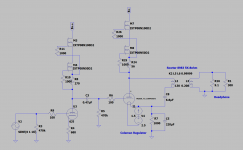
Here is what I have by way of schematic, but it is not comprehensive.


Another thing you may find helpful, depending on the headphones being used, is to put a 6 ohm resistor in series with a 2 ohm resistor on the 8 ohm output, with the 2 ohm end at ground. This gives you a padded output for hyper sensitive headphones with a far lower noisefloor. This is really helpful for Grados and IEMs.
I'll keep that in mind audiowize. I typically use 300ohm headphones,but if I go more sensitive, I'll alter to a padded output.
Could the unrectified AC filament supply be coupling with the DC plate supply/signal of your output tubes?
As best as I can tell, you've got rectification, filtering and regulation of the filament supply together on the sides of chassis. They are connected to the heater windings via longish wiring running from the sides to the center of the amp. As I read him, Rod Coleman recommends a different setup: rectify and filter close to the heater windings. From Rod's installation guide:
"4.6. Wiring between rectifiers, snubbers, and C1 capacitor: keep these really tight. A 1.2A dc supply runs 6A pulses through these! The pulses will electromagnetically couple into your signal circuits if these are long.
4.7. Transformer to rectifiers: keep shorter than 75mm, same reason as above.
4.8. Raw-DC wiring from rectifiers/capacitors to Regulator's board: you can make these up to 2 metre long, and mount in a different chassis."
Maybe try moving the "raw dc" board to the center of the chassis. Might help.
Unrelated questions: Are the larger Solen caps the parafeed output caps? How/where do the parafeed caps connect to the plate and the output transformer? I can't tell from the wiring pic. I'm admiring your layout, but can't see this part of your circuit.
cheers, Derek
Thanks, Derek. Yes I'm aware I am violating RC's recommendations. I made compromises in terms of layout such that I could use a smaller chassis with a particular aesthetic, so I deserve any noise I get 🙂 interestingly though, with the longish runs of filament regulator wiring, I would expect coupling of 120Hz rectifier pulses to a greater degree, but that doesn't seem to be much of an issue.
Yes, the larger Solen caps are the parafeed caps. You can see on the schematic above, connect at the bottom of the OPT primary and top of the cathode resistor.
Thanks for the schematics. Do the 6J5 heaters have any ground reference?
No problem, thanks for taking the time to help. Yes they do, a virtual center tap using two 100ohm resistors to ground.
Yes, the larger Solen caps are the parafeed caps. You can see on the schematic above, connect at the bottom of the OPT primary and top of the cathode resistor.
Many thanks. I remember a Broskie schematic with the parafeed cap in that location, but yours is the first amp I've seen that is actually wired that way. Beautiful layout and amp.
cheers, Derek
Many thanks. I remember a Broskie schematic with the parafeed cap in that location, but yours is the first amp I've seen that is actually wired that way. Beautiful layout and amp.
cheers, Derek
Thank you, Derek! Take care.
The cap is often less visually offensive when it's put between cathode and the bottom of the output transformer primary winding, but it is serving the identical function as it would if you put it between plate and OT.
I prefer to put it between plate and OT because it takes nearly all the DC voltage potential off the transformer primary. For a low voltage amp this doesn't really matter at all.
I prefer to put it between plate and OT because it takes nearly all the DC voltage potential off the transformer primary. For a low voltage amp this doesn't really matter at all.
Hello,
I am building a VT25A power amp which also uses the Rod Coleman supplies.
I had the cathode cap of the power tube just connected at the UX4 socket and the older side kind of up in the air. Without that cap connected at the right spot the Coleman circuits will not work.
Greetings, eduard
I am building a VT25A power amp which also uses the Rod Coleman supplies.
I had the cathode cap of the power tube just connected at the UX4 socket and the older side kind of up in the air. Without that cap connected at the right spot the Coleman circuits will not work.
Greetings, eduard
Attachments
Resurrecting this thread to ask for a technical explanation for a similar phenomenon to the one described back in May 2020.
The 45 parafeed headphone amplifier discussed in the first post of this thread was rebuilt for speakers, with a new custom mains transformer to bias the 45 near max plate dissipation with a FET CCS load.
Just to recap, the negative terminal of the OPT primary was taken to the top of the 45 cathode in this build. It was understood from previous discussion that the Coleman regulators require an AC ground reference, a bypass cap in order to function correctly, which was presumably the issue with the 60Hz noise I was experiencing.
I included the bypass caps the second go-around, however from my experiments, I found that that the amount of capacitance did not affect the frequency response as they were not "in the signal path". Okay, then I'll use a reasonably-sized film cap - 4.7uF gave me full bandwidth up to transformer limitations.
Well 4.7uF across the cathode was too little, the capacitive reactance at 60Hz too high, which resulted in a large 60Hz peak on FFT in the left channel, similar to my original issue, only audible with sensitive headphones, inaudible on my speakers. Some improvement in the noise measurement with an additional 20uF of film caps, but still a very large peak. Next a 100uF electrolytic, more improvement, but still significant 60Hz noise on FFT.
Well I switched over to a 220uF bipolar electrolytic, and now the 60Hz peak is buried in the noise floor. BUT the sound is undoubtedly degraded with the change as opposed to the film caps.
So my question is - how is the electrolytic affecting the sound so drastically without the cap being in the signal path, per se? Seems the smart engineering decision is to use the 220uF electrolytic, but it is disappointing that the sound quality suffers so significantly compared to a lower value film.
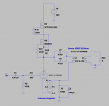
For reference, the output stage is setup as below.

Of note, the right channel is completely devoid of power supply noise on FFT even with a 4.7uF film.
The 45 parafeed headphone amplifier discussed in the first post of this thread was rebuilt for speakers, with a new custom mains transformer to bias the 45 near max plate dissipation with a FET CCS load.
Just to recap, the negative terminal of the OPT primary was taken to the top of the 45 cathode in this build. It was understood from previous discussion that the Coleman regulators require an AC ground reference, a bypass cap in order to function correctly, which was presumably the issue with the 60Hz noise I was experiencing.
I included the bypass caps the second go-around, however from my experiments, I found that that the amount of capacitance did not affect the frequency response as they were not "in the signal path". Okay, then I'll use a reasonably-sized film cap - 4.7uF gave me full bandwidth up to transformer limitations.
Well 4.7uF across the cathode was too little, the capacitive reactance at 60Hz too high, which resulted in a large 60Hz peak on FFT in the left channel, similar to my original issue, only audible with sensitive headphones, inaudible on my speakers. Some improvement in the noise measurement with an additional 20uF of film caps, but still a very large peak. Next a 100uF electrolytic, more improvement, but still significant 60Hz noise on FFT.
Well I switched over to a 220uF bipolar electrolytic, and now the 60Hz peak is buried in the noise floor. BUT the sound is undoubtedly degraded with the change as opposed to the film caps.
So my question is - how is the electrolytic affecting the sound so drastically without the cap being in the signal path, per se? Seems the smart engineering decision is to use the 220uF electrolytic, but it is disappointing that the sound quality suffers so significantly compared to a lower value film.
For reference, the output stage is setup as below.

Of note, the right channel is completely devoid of power supply noise on FFT even with a 4.7uF film.
Last edited:
Please disregard my question above, digging deeper on the forum, seems I am not the only one that has found the bypass cap is still audible in the above parallel feed setup. I suppose an electrolytic it will have to be, I will choose it over a 60Hz hum. Size limitations preclude a film cap, unfortunately.
- Home
- Amplifiers
- Tubes / Valves
- Transformer Magnetic Coupling - 60Hz on one channel of brand new build, am I SOL?


