Looking for some advice, pretty disappointed in the conclusion I am coming to.
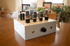
Just finished a very involved 45 parafeed dedicated headphone amplifier using Sowter transformers. The mains is a custom job by them, pictures below.
Mains and output transformers are oriented 90 degrees to one another. The left channel is completely silent. The right has a VERY audible 60Hz buzz. Shorting the inputs has no effect, neither does shorting the input tube grid to ground, or removing the input tubes entirely. I've isolated it to the output stage, and it persists even with no tubes in the amp, leading me to believe it is magnetic coupling from the mains transformer, despite the orientation.
Short of rebuilding the amplifier, is there anything that can be done? A lot of work went into this build, so a pretty disappointing outcome. The sound is great otherwise, but as a headphone amp, it is very loud in the right channel, can be heard easily above music playing.
Thanks for the help.
Attachments

Last edited:
With that layout, you shouldn't only get that in one channel.
This looks like it's cap coupled with cathode bias and active loads on all the tubes?
What happens if you put a clip lead across the grid leak on the right channel?
Since you have alligator clips on your parallel feed caps, you could swap the active loads temporarily just to see what happens.
This looks like it's cap coupled with cathode bias and active loads on all the tubes?
What happens if you put a clip lead across the grid leak on the right channel?
Since you have alligator clips on your parallel feed caps, you could swap the active loads temporarily just to see what happens.
I'm also very suspicious of your mains wiring. Is the side that's noisy the side where all the mains wiring is running?
Looking for some advice, pretty disappointed in the conclusion I am
Mains and output transformers are oriented 90 degrees to one another. The left channel is completely silent. The right has a...
Thanks for the help.
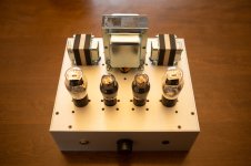
First thing I'd do... Leaving the transformers installed as they are... Temporarily swap their primary wires L/R. If the hum moved to the left, and the right is now clean, you know it's not a tranny, it's what is feeding it. Hopefully the hum will move to the left, because that proves those expensive Sowters are both fine where they are. If the hum is still on the right. Then I'd remove the right tranny and wire it up a foot or two feet away from anything electrical to see if it's induction or not. But before that, look for any AC power cables near the right side wiring, since your hearing 60 hZ and not 120 hZ, It does look like a mains cord is crossing paths with the right channel wiring there.
Last edited:
In the photo they did a good symmetry job. But they did not run the black ground wire from the star to the board on the left side of the picture, just the right.
John
John
With that layout, you shouldn't only get that in one channel.
This looks like it's cap coupled with cathode bias and active loads on all the tubes?
What happens if you put a clip lead across the grid leak on the right channel?
Since you have alligator clips on your parallel feed caps, you could swap the active loads temporarily just to see what happens.
Correct, it is an all active load, cap coupled, parafeed output. Right now it is connected in a "Western Electric" output, so there is no bypass cap on the output tube.
Shorting the input or output tube grid to ground makes no difference.
I swapped active loads and it swapped sides! That is encouraging, looks like I have more digging to do.
I'm also very suspicious of your mains wiring. Is the side that's noisy the side where all the mains wiring is running?
All of that AC wiring is actually near the left channel, which is silent.
Can you post the schematic here?
It hums loudly with NO tubes installed at all?
Yes, loudly with no tubes installed at all. A detailed schematic isn't available, what I have I don't think would be of much help.
Last edited:
First thing I'd do... Leaving the transformers installed as they are... Temporarily swap their primary wires L/R. If the hum moved to the left, and the right is now clean, you know it's not a tranny, it's what is feeding it. Hopefully the hum will move to the left, because that proves those expensive Sowters are both fine where they are. If the hum is still on the right. Then I'd remove the right tranny and wire it up a foot or two feet away from anything electrical to see if it's induction or not. But before that, look for any AC power cables near the right side wiring, since your hearing 60 hZ and not 120 hZ, It does look like a mains cord is crossing paths with the right channel wiring there.
I believe I executed an equivalent experiment to yours above by swapping which CCS load fed which OPT. I fed the right to the left OPT and vice versa. The noise moved to the left side, which would lead me to believe it is not the transformer. What a relief!
Last edited:
In the photo they did a good symmetry job. But they did not run the black ground wire from the star to the board on the left side of the picture, just the right.
John
Sorry the picture is not clear, there is no ground to either board, they are Rod Coleman filament regulators which are floating. The ground wire you are seeing is a center-tap for the input tube heaters.
I think you've found the problem. Try a plate loading resistor on the noisy channel temporarily.
Thank you all for helping me troubleshoot, yes I suspect the issue may lie with the R channel output CCS board, I'll take a closer look.
Much appreciated!
Much appreciated!
After more thorough troubleshooting, I've discovered the cause, the noise is being injected from the right channel Rod Coleman regulator (swapping the regulator connections moved the noise). As it turns out, with the "Western Electric" style parafeed output, swapping the parafeed cap connections was not a reliable test in retrospect.
Anyhow, very confident this is the issue, I've emailed Rod to get his thoughts on a possible cause, but any thoughts are welcome from those who are experienced with them.
Anyhow, very confident this is the issue, I've emailed Rod to get his thoughts on a possible cause, but any thoughts are welcome from those who are experienced with them.
The odyssey continues...
I have determined my 60Hz noise is being coupled within my Sowter custom mains transformer, not the Coleman regulator. Swapping the two 6.3V / 5A windings between the two raw DC boards confirmed this.
The lead Rod Coleman gave me was to check for leakage capacitance from primary to secondary of the filament winding, his concern being common mode noise being coupled across the transformer. I haven't pursued this yet, but even if that were the case, I don't know if there is much to be done other than having Sowter wind me another transformer. The Sowter mains has an electrostatic screen as well which is grounded to the chassis. Ungrounding the screen had no effect.
Here are some measurements.
First, the left and right channels with no cathode bypass caps. This is the situation in which the noise is clearly audible on one channel (the left in this case, since they windings were swapped), but the other channel is silent to the ear. I think you will see why in the plots.
Left:

Right:

Now here are the two channels with the cathodes bypassed.
Left:

Right:

As you can see, the noise pattern on the right channel is unchanged while the excessive noise on the left channel is now gone. There is still a 60Hz noise pattern with the cathodes bypassed, but you can see the pattern is now very similar across both channels and significantly attenuated to around -80dBFS.
I tried running one of the 6J5's heaters off my DC bench supply to see if the noise was related to heater-to-cathode leakage or the AC heater wiring, and that does not appear to be the case, there was no change.
I am wondering if this type of coupled noise is to be expected or if I should contact Sowter? Odd that it is only across one winding.
I welcome I thoughts or advice, thank you.
I have determined my 60Hz noise is being coupled within my Sowter custom mains transformer, not the Coleman regulator. Swapping the two 6.3V / 5A windings between the two raw DC boards confirmed this.
The lead Rod Coleman gave me was to check for leakage capacitance from primary to secondary of the filament winding, his concern being common mode noise being coupled across the transformer. I haven't pursued this yet, but even if that were the case, I don't know if there is much to be done other than having Sowter wind me another transformer. The Sowter mains has an electrostatic screen as well which is grounded to the chassis. Ungrounding the screen had no effect.
Here are some measurements.
First, the left and right channels with no cathode bypass caps. This is the situation in which the noise is clearly audible on one channel (the left in this case, since they windings were swapped), but the other channel is silent to the ear. I think you will see why in the plots.
Left:
Right:
Now here are the two channels with the cathodes bypassed.
Left:
Right:
As you can see, the noise pattern on the right channel is unchanged while the excessive noise on the left channel is now gone. There is still a 60Hz noise pattern with the cathodes bypassed, but you can see the pattern is now very similar across both channels and significantly attenuated to around -80dBFS.
I tried running one of the 6J5's heaters off my DC bench supply to see if the noise was related to heater-to-cathode leakage or the AC heater wiring, and that does not appear to be the case, there was no change.
I am wondering if this type of coupled noise is to be expected or if I should contact Sowter? Odd that it is only across one winding.
I welcome I thoughts or advice, thank you.
Last edited:
A 6.3V transformer winding is 60Hz noise!
Out+ from the Coleman regulator is expected to go to a cathode bypass cap. You need the cathode bypass cap. You're debugging a problem that isn't a problem.
Out+ from the Coleman regulator is expected to go to a cathode bypass cap. You need the cathode bypass cap. You're debugging a problem that isn't a problem.
Last edited:
So one channel requires cathode bypass and the other doesn't? In the first two plots above, there is no noise on one channel without bypass while the other is at 120mVpp, -50dB. Why would it be asymmetrical?
Not trying to be snarky and I appreciate your help, just trying to understand the issue for future reference. According to Coleman, I should not be seeing 120mVpp out of the regulator. How would that noise be handled if I were using fixed bias?
Not trying to be snarky and I appreciate your help, just trying to understand the issue for future reference. According to Coleman, I should not be seeing 120mVpp out of the regulator. How would that noise be handled if I were using fixed bias?
Last edited:
If you were using fixed bias, you would have one end of the filament grounded. That's the problem, you don't have either end of the filament regulator at AC ground. The application notes show this as a likely necessity. This is also a problem for amp performance.
Okay, understood. In that case, I will leave the cathodes bypassed and move on. Was concerned that I was covering up an issue rather than addressing it. I suppose the -80dB noise is likely AC coupling within the amp. In any case, I can't hear it. Thanks again.
I'm glad you didn't have to rip out the OTs!
For a headphone amp, I'd look at a lower tap on the OPT to see if that noise goes down.
For a headphone amp, I'd look at a lower tap on the OPT to see if that noise goes down.
- Home
- Amplifiers
- Tubes / Valves
- Transformer Magnetic Coupling - 60Hz on one channel of brand new build, am I SOL?