I would like to make and use a transformer that would do a 1:60 (or 60 to 1) for audio frequencies, to drive a load of approx. 7.5 K (so not very much current). I would expect to feed the primary with about 1V rms and "see" 60 V rms at the secondary. Expected frequency range would be audio, so from 20Hz to 20KHz. Would someone please tell me what sort of item I would be looking at? Thanks
PS forgot to say:
would it be iron core or air?
would I be able to run a DC through the primary or would the DC "saturate" something or do something bad?
would I be able to have another coil similar to the primary to run an opposite DC ?
would it be iron core or air?
would I be able to run a DC through the primary or would the DC "saturate" something or do something bad?
would I be able to have another coil similar to the primary to run an opposite DC ?
You're looking at an extremely expensive piece of custom iron there.
60:1 is acheivable (I have worked comminications mic transformers that do 200:1, but those were 300Hz to 3KHz and microvolt rated only), but for the full HiFi frequency range with a dielectric strength to handle 60VRMS (~85V p-p) will be large, have a rare earth core and likely cost the better part of 500+ quid.
If such a beast is out there already, I'd like to know 🙂
And for DIY'ing one, in this case, if you have to ask..... 😉
Cheers!
does it have to be a transformer?
gain of 60 (+36dB) low power amplifier.
You are only looking for 1/2W and using 300V driver devices from +-100Vdc should hit your target.
gain of 60 (+36dB) low power amplifier.
You are only looking for 1/2W and using 300V driver devices from +-100Vdc should hit your target.
I am trying to avoid the transistor stage because I do not know how to do it. All my SPICE models return quite high distortion (0.2 %) for 40 V rms. Remember my questions about high hfe transistors at the 150V Vceo range? I am not using more than 1 transistor per "sub-stage" (because I am stubborn), so my stages are simple common emitter/common collector. But at those voltages (160V+) and low HFEs (100-120) SPICE tells me there is significant distortion (0.2% at best). SPICE also reports that my output buffer stage has 0.002% distortion which is great, all I need is the driver stage now.
So I just went downstairs and hooked up a toroidal power transformer (230V / 2x25V 80VA) to have a go at some practical measurements using signal generator and oscilloscope. I used a MJE15030 to drive the two secondaries in series which have a 2.3 Ohm resistance. I measured the signal at the primary and got a 4.3:1 gain. However gain falls rapidly from 100Hz or so, stays stable up to about 10KHz, peaks at 30KHz (or was it 300KHz?) to something really silly, and then it falls off again.
By the way, I had wired up the secondaries on the DC path, so there was a constant current flowing through the secondary, not sure if that would have any effect one way or the other.
So using that ready-made, cheap-ish toroidal I observed:
1. The secondary windings have very low resistance and are hard to drive (the MJE got burning hot and had to put it on a cooler, idle current was 1.3A !!!).
2. there is a problem with frequencies below 100Hz.
3. Do I need an iron core?
4. Could we wind more wire on the secondary to increase its impedance (at least at low frequencies) ? I guess we woult hen have to increase the turns on the primary but as it is the primary has 25 Ohm resistance, even if it rises to 20 times that it would still be OK.
You're looking at an extremely expensive piece of custom iron there.
60:1 is acheivable (I have worked comminications mic transformers that do 200:1, but those were 300Hz to 3KHz and microvolt rated only), but for the full HiFi frequency range with a dielectric strength to handle 60VRMS (~85V p-p) will be large, have a rare earth core and likely cost the better part of 500+ quid.
If such a beast is out there already, I'd like to know 🙂
And for DIY'ing one, in this case, if you have to ask..... 😉
Cheers!
I infer that the dielectric determines the maximum voltage swing? I thought it was related to power only ?
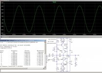
Using cascode techniques, achieving a reasonably low THD is not difficult.
Here is a quick example yielding 0.06% THD on the stated load (is much lower unloaded).
Getting comparable results from a transformer would be near impossible, even with ferrite.
And I am not even mentionning the frequency response issues.
The circuit is unelegant with coupling caps, etc but it's just an example, and you can easily clean it up.
Using a ferrite transformer of 1cm² core area, you would need about 35000 turns to obtain a response to 20Hz without exceeding an induction of 0.2T (which is far from small signal).
Attachments
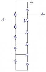
Thanks for the tips. I have so far been avoiding using more than 1 active device per stage and the cascode circuits use more than 1🙂 However, I am now toying with a simple cascode circuit, it seems we are using more than one transistors in series to share the voltage whilst using small signal transistors that have very high hfe. I am playing with 4 NPNs chained together over 160 Volts on SPICE. I am trying to divide the voltage drops equally amongst the 4, I have not read any documents on how to do this, just experimenting and see how it goes. I have got it to yield less than 0.01 % with x10 and at 12 V rms. I cannot go to 40+ V rms without incurring a 0.2% THD, so I am experimenting more. I sort of understand my circuit but I cannot say that I even begin to understand yours 🙂 The trouble is my circuit is very volatile, very sensitive to small biasing changes, according to the simulation at least. I hope the simulation is accurate and am not wasting my time.
Attachments
I infer that the dielectric determines the maximum voltage swing? I thought it was related to power only ?
For the ratios and interleave involved here for full response on a PCB sized core, we're probably talking 46-48 gague wire. A few tens of volts breakdown.
Cheers!
Thanks for the tips. I have so far been avoiding using more than 1 active device per stage and the cascode circuits use more than 1🙂 However, I am now toying with a simple cascode circuit, it seems we are using more than one transistors in series to share the voltage whilst using small signal transistors that have very high hfe. I am playing with 4 NPNs chained together over 160 Volts on SPICE. I am trying to divide the voltage drops equally amongst the 4, I have not read any documents on how to do this, just experimenting and see how it goes. I have got it to yield less than 0.01 % with x10 and at 12 V rms. I cannot go to 40+ V rms without incurring a 0.2% THD, so I am experimenting more. I sort of understand my circuit but I cannot say that I even begin to understand yours 🙂 The trouble is my circuit is very volatile, very sensitive to small biasing changes, according to the simulation at least. I hope the simulation is accurate and am not wasting my time.
You don't need to put multiple devices in series, you can easily find devices with 300V Vce. But, in order to reduce distorsion, you need the cascode configuration. 5V across the lower device is more than sufficient.
And if you want meaningful simulation results, you have to include the load; results will be quite different.
And you also need to simulate your output buffer with a source impedance matching that of the voltage amplifier. Results will significantly differ too, from a zero ohm source.
I can not find > 150 Vceo devices with any respectable Ft and Hfe, best device seems to be the MJE15030/15032 with hfe of 120-150 up to 1 A.
Why do you say that cascode reduces distortion? Is it because each transistor will "see" a smaller Vce over the same output voltage swing?
In my simulation I will include source impedance and outbut buffer impedance. But I still need to understand why and how cascode works better than a single transistor (other than allowing us to use much lower Vceo transistors).
The ubiquitous MJE340/50 are more than adequate. You can also turn to better alternative, 2SAxxxx/2SCxxxx, they have been discussed in the Solid state forum.I can not find > 150 Vceo devices with any respectable Ft and Hfe, best device seems to be the MJE15030/15032 with hfe of 120-150 up to 1 A.
Some BFQxxx BFNxxx intended for HD-video output stages are also usable
No, it is simply because the pilot transistor sees no delta-Vce.Why do you say that cascode reduces distortion? Is it because each transistor will "see" a smaller Vce over the same output voltage swing?
A single-ended alternative is also possible, and takes you below 0.01%:
Attachments
Hi, I ran your latest circuit into my Sim and got 0.006%.
However, without wishing to sound awkward, your circuit has an very big gain stage followed by an output buffer and a negative feedback loop to tame distortion.
But my original premise was to avoid exactly that, the negative feedback, as well as avoid having multiple transistors on the same stage, eg cascode or regulated voltage sources, current mirrors, constant current sources etc.
So I looked at the possibility of a transformer to do the 1:60 but I am told this is almost impossible. Then we looked at cascode to be able to use BC548s with 150V supply rails because those have higher hfe than high voltage transistors and also because of "delta-Vce" (what does that mean ?).
I have come up with very simple cascode circuits using BC548 with 160V rails and am still experimenting (on simulation). I can get down to 0.009% so far, but not on a 7K load. Still trying to understand how it works.
- Status
- Not open for further replies.
- Home
- Design & Build
- Parts
- Transformer help