Transformer Distorsion THD
Hi people 🙂
has someone ever measured the distorsion of an audio-transformer to AudioPrecision (THD vs Power) ?
and for the transformers interstage (THD vs Vout) ? 😕
I have tried to look for in the web but I have found anything of nothing
Thanks 😀
Hi people 🙂
has someone ever measured the distorsion of an audio-transformer to AudioPrecision (THD vs Power) ?
and for the transformers interstage (THD vs Vout) ? 😕
I have tried to look for in the web but I have found anything of nothing
Thanks 😀
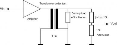
I am planning to do such measurement. I will use this arrangement:
low distortion audio generator - 100 Watt transistor power amplifier - transformer secondary : transformer primary - 100 Watt dummy load - voltage divider - distortion analyzer
The dummy load is a resistor with T^2 x 8 ohm resistance, where T is the transformer turns ratio.
low distortion audio generator - 100 Watt transistor power amplifier - transformer secondary : transformer primary - 100 Watt dummy load - voltage divider - distortion analyzer
The dummy load is a resistor with T^2 x 8 ohm resistance, where T is the transformer turns ratio.
What are your aims in wanting to do such measurements ? Reasons ? Magnetics is as wide as the universe.
richj
richj
As for myself, I am interested in the level/frequency dependency of the distortion magnitude and spectrum. Tubes and transformers are the two dominant nonlinear components in a tube amplifier. We know the characteristics of tubes very well, but we know very little about a custom-made transformer. Therefore it makes sense for me to measure a transformer off-circuit.
BTW I measure each resistor before soldering in the circuit. And for a good reason: I found a Mills MRA-12 wirewound nominal 33k, actual 66k.
BTW I measure each resistor before soldering in the circuit. And for a good reason: I found a Mills MRA-12 wirewound nominal 33k, actual 66k.

I do believe there is an Edcor vs. Hammond THD shootout somewhere. Was it one of Tubelab's pages? I can't find the link right now 😕
Cheers!
Cheers!
Geek said:I do believe there is an Edcor vs. Hammond THD shootout somewhere. Was it one of Tubelab's pages? I can't find the link right now 😕
Cheers!
Tubelab has some SE transformer tests, I recall...
Funwithtubes has some Push-Pull tests. I linked one below:
http://www.angelfire.com/electronic/funwithtubes/Amp-Monoblock_UL.html
Since the 100w transistor amplifier isn't linear, I'd suggest measuring the 'THD' opf that and subtracting that from the transformer results.
Some parts may cancel, some may add, but with the proposed thest you won't just be measuring the transformer.
James
Some parts may cancel, some may add, but with the proposed thest you won't just be measuring the transformer.
James
Don't forget that in most tube output circuits that use a transformer there is DC current flowing in the primary side of the transformer. This can have a large effect on the performance of the transformer. The DC current in a single ended output stage will mean that you need a transformer with a large core with a gap to prevent over heating and saturation of the core material.
In a PP circuit the DC current is less of a problem because power is generally supplied to the center tap and the plate connections to the ends of the coil winding causing the DC flux level in the core to be near 0.
If you don't put DC bias on the transformer during the measurement the distortion will not be the same in the circuit.
Icsaszar,
Assume that an output transformer is relatively the same performance, no matter whether you drive the secondary or the primary.
A typical solid state amplifier might have a damping factor of 50 relative to an 8 Ohm loudspeaker.
8 / 50 = 0.16 Ohms solid state amplifier Z out.
You are driving the secondary with 0.16 Ohms.
Imagine that instead you drive the 5k Ohm primary with 5,000 / 50 = 100 Ohms (damping factor = 50).
That is very different than driving the 5k Ohm primary with 1,000 Ohms (like a triode's plate impedance, rp, of 1k; damping factor = 5).
The distortion, frequency response, square wave response, etc. will all be very different when you drive the primary with
100 Ohms, versus driving it with 1000 Ohms.
So, drive the 8 Ohm secondary with Either 0.16 Ohms, or drive it with 8 x 5 = 40 Ohms.
You will get realistic answers of the transformer's distortion, frequency response, and square wave if you do two things:
1. Put a 40 Ohm resistor in series with the solid state amplifier output to the transformer primary.
2. Put a 5k Ohm resistor across the 5k primary.
It is true, you may not own a solid state amplifier with a voltage output that can drive the 6:1 voltage division of the 8 Ohm tap and the 40 Ohm series resistor.
But, that is the way it goes (I can not fool physics), you might have a physics trick up your sleeve.
The output transformer is not perfect, but you have to test it in the 'same environment' that it will be used.
Examples:
A 5k to 8 Ohm transformer, 625:1 impedance ratio . . .
1. Secondary Inductance that is driven by either 0.16 Ohms, or by 40 Ohms.
2. Distributed Capacitance of the primary that reflects to be 625 x 'primary capacitance' onto the secondary; with the secondary driven by either 0.16 Ohms, or by 40 Ohms.
As mentioned in earlier posts by others on this thread, there are additional issues:
Quiescent DC current on the primary of single ended transformers.
Any medium or large un-balanced quiescent DC current on a push pull transformer (medium or large depends on Amp x Turns versus lamination volume/weight and core material type).
Just my opinions
Last edited:
HiIcsaszar,
Assume that an output transformer is relatively the same performance, no matter whether you drive the secondary or the primary.
A typical solid state amplifier might have a damping factor of 50 relative to an 8 Ohm loudspeaker.
8 / 50 = 0.16 Ohms solid state amplifier Z out.
You are driving the secondary with 0.16 Ohms.
Imagine that instead you drive the 5k Ohm primary with 5,000 / 50 = 100 Ohms (damping factor = 50).
That is very different than driving the 5k Ohm primary with 1,000 Ohms (like a triode's plate impedance, rp, of 1k; damping factor = 5).
The distortion, frequency response, square wave response, etc. will all be very different when you drive the primary with
100 Ohms, versus driving it with 1000 Ohms.
So, drive the 8 Ohm secondary with Either 0.16 Ohms, or drive it with 8 x 5 = 40 Ohms.
You will get realistic answers of the transformer's distortion, frequency response, and square wave if you do two things:
1. Put a 40 Ohm resistor in series with the solid state amplifier output to the transformer primary.
2. Put a 5k Ohm resistor across the 5k primary.
It is true, you may not own a solid state amplifier with a voltage output that can drive the 6:1 voltage division of the 8 Ohm tap and the 40 Ohm series resistor.
But, that is the way it goes (I can not fool physics), you might have a physics trick up your sleeve.
The output transformer is not perfect, but you have to test it in the 'same environment' that it will be used.
Examples:
A 5k to 8 Ohm transformer, 625:1 impedance ratio . . .
1. Secondary Inductance that is driven by either 0.16 Ohms, or by 40 Ohms.
2. Distributed Capacitance of the primary that reflects to be 625 x 'primary capacitance' onto the secondary; with the secondary driven by either 0.16 Ohms, or by 40 Ohms.
As mentioned in earlier posts by others on this thread, there are additional issues:
Quiescent DC current on the primary of single ended transformers.
Any medium or large un-balanced quiescent DC current on a push pull transformer (medium or large depends on Amp x Turns versus lamination volume/weight and core material type).
Just my opinions
on other thread here, but in the past also ( as you know) there are tests results on this method.
ANd solution for dc current (almost ) easy to do
It is smart and efficent test if well dimensioned.
You need a good audio card, Arta or Audio analyzer. Of course the Audio precision is the best
Walter
A solid state amplifier with lots of volts out, a 40 Ohm power resistor, and a DC constant current source are all that is needed to set up the secondary side of the equation.
To test a 15 Watt transformer, a solid state amplifier of 6 x 15 watts = 90 watts, and a 40 Ohm resistor rated for at least 100Watt dissipation is needed (more than 100 Watt dissipation if you do not want to put burn marks on your test bench).
If the output transformer is 5k to 8 Ohms, and is going to be used with 60mA DC quiescent current, then when the method is to drive the secondary, the current source needs to have 1.5 Amps.
All of this is easy for some, but not for others.
The measurement equipment is usually the easy part, the solid state amp and DC constant current source are not so easy for many thread readers.
Please note that . . .
For a single ended triode amplifier that does not use negative feedback, the output stage performance will never be better than the sum of the parts (the output tube and the output transformer).
An exception to the total amplifier performance being better than that, is if there is some cancellation of the 2nd harmonic distortion (due to the 2nd HD of the driver, versus the 2nd HD of the output stages). They are in opposite phase, so they partially cancel; but the cancellation is load dependent. Loudspeaker load varies with frequency, so also does the partial cancellation of the driver and output stage 2nd HD.
Just my opinions
Last edited:
At the moment I haven' time to explain the proto I sent in other thread to drive the secondary with dc.
It is not so comlicated but everyone can spend some money to have a proper test setup
A ss amp kit with good performance cost arounf 50$ and can deliver more thant 20 volt on 8 ohm with a low distortion ( THD and THD vs Frequency)
If I have a OT with ratio 22:1 (p.e.) I can deliver 440 Vrms that is fine to test the OT
Walter
Lets consider a 15 Watt 5k to 8 Ohm transformer with 0.4 Ohms secondary DCR.
0.4 Ohms x 1.5 Ohms = 60 mV DC.
Some solid state amplifiers might not like that, even if you put a 40 Ohm resistor in series.
Even if there is no damage, the amplifier offset feedback circuit will have to compensate for 60mV / 6 = 10mV.
And, using a series capacitor to isolate the solid state amplifier from the DC offset, will require a very large capacitance capacitor to test the 10Hz to 100 Hz frequency response and distortion of the transformer.
Sometimes doing it right is more complex than when it was first considered.
Dmitrij_S,
Simulations can be very helpful, but . . .
Pretend you just had a pair of output transformers delivered to your house from half way around the world.
The manufacturer only gave these specifications: 5k to 8 Ohms, and 4kg weight.
Oh . . . did I mention that the transformers are potted.
How do you do a simulation that tells you more about those output transformers?
I am of the opinion that . . .
Either you do a lot of measurements of the transformer itself,
Or, you install the transformer into a known amplifier and do lots of measurements of the amplifier performance.
If you measure the 5k:8R transformator in the reverse arrangement (driving the secondary, measuring the attenuated primary voltage), why don't add a series 8R power resistor to the driving amplifier output? And load the primary with 5k?
You have to test a single ended transformer with the same conditions that it will be used (or in the same reverse conditions that it will be used ).
You do not drive a 5k primary with a plate impedance, rp, of 5k, because:
The damping factor will be very low, only 1.0; the low frequency bandwidth will be very limited by the primary inductance; and the high frequency bandwidth will be very limited by the primary distributed capacitance.
And, driving the 8 Ohm secondary with 8 Ohms will also give a low damping factor of 1.0, and will limit the low and high frequency responses at the 5k primary.
But you are correct, when you test the 5k to 8 Ohm transformer in reverse, you do load the primary with 5k Ohms.
Instead, for example, you drive the 5k primary with a plate impedance, rp, of 1.25k Ohms. That gives a damping factor of 4.0; and the low frequency bandwidth goes 4 times lower, and the high frequency bandwidth goes 4 times higher; versus driving it with 5k Ohms.
And you load the 8 Ohm secondary tap with 8 Ohms.
Suppose you want to test by using the reverse method:
So you drive the 8 Ohm secondary with 2 Ohms, and load the primary with 5k Ohms. That gives the same damping factor of 4.0, and the low frequency bandwidth and high frequency bandwidth are extended.
A transformer needs the drive impedance and the load impedance to give the proper damping factor and low and high frequency bandwidths.
Example, 1000pF distributed capacitance on the 5k primary, on the secondary will be multiplied by the turns ratio.
5k to 8 Ohms = 25:1 turns ratio. 500pF x 25 = 25,000pF at the secondary.
Of course there are many other factors that affect the transformer's performance, such as:
Leakage reactance, primary DCR, secondary DCR, lamination saturation, etc.
Last edited:
The last one would be my preferred way. It should not be that difficult to create a simple prototype (maybe just the output stage) to test the transformer with a real application.Dmitrij_S,
Simulations can be very helpful, but . . .
Pretend you just had a pair of output transformers delivered to your house from half way around the world.
The manufacturer only gave these specifications: 5k to 8 Ohms, and 4kg weight.
Oh . . . did I mention that the transformers are potted.
How do you do a simulation that tells you more about those output transformers?
I am of the opinion that . . .
Either you do a lot of measurements of the transformer itself,
Or, you install the transformer into a known amplifier and do lots of measurements of the amplifier performance.
- Home
- Amplifiers
- Tubes / Valves
- Transformer distortion (THD)