Hi All,
I asked this over at the Gainclone Forum, but have got little response. I know that there is a great deal more experience over here on the Valve forum concerning the use of transformers.
I started out building Gainclones, and was fairly happy with the result until I built my first Valve amp. I never looked back, but have ended up with Class A PP amps running a constant 200W at idle which is a bit painful to live with. So I started to thinking what were the issues I encountered with the Gainclones in the first place.
I think the main issue is high frequency noise causing slewing problems which manifest as saturation of the output stages. By using transformers all of the radio frequency crud should be eliminated (I will also put an inductor on the input as well).
I had one of my valve buffered gainclones eat a set of speakers and have been a whole lot happier knowing that there was a nice transformer protecting my precious vintage drivers. Also my speakers are all 4ohm, so I could introduce a bit of a step up to give the Gainclones an easier ride.
In my valve amps I have all but eliminated coupling caps (to great benefit) through the use of transformers, so I can see the benefits of eliminating them in the gainclone.
Anyway what does anyone think of the idea. Any constructive suggestions.
Shoog
Hi,
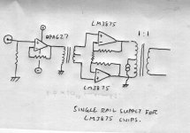
I wonder why you drew a current source in the center tap of the output transformer? Is that to force the output stage of the LM3875 into class A? I'd be a bit cautious with this approach, because it rapidly increases the dissipation of the chip. If you have high frequency interference problems, then you must eliminate that cause. Transformers can act as antennas too. Saturation of the output stage is very unlikely unless the interference is so bad that the amp clips. In general, I'd be a bit wary for trying out several "solutions" before you have identified the problem well enough to be tackled. Could you post some more details about the problematic gainclones?
Mind you that the LM amps expect a defined load at high frequency, so a snubber/zobel across the output transformer's primary is required, otherwise the leakage inductance of the transformer will challenge your amp's gain and phase margins, and possibly make it unstable.
The idea of the CCS was to force the outputs into class A. Running at about 40mA would push it out of crossover for the first 1.5watts or so, which would be more than adequate and would not place much heat on the chips (well heatsinked of course). It is claimed to improve performance, and I have never previously tried it so I though I would give it a stab.
I never really had serious issues with my Gainclones, but Joe Rasmussen did some interesting analysis about the high frequency gain margin and slewing of these chips which suggests that they are much better off with a bit of high frequency filtering.
Shoog
I never really had serious issues with my Gainclones, but Joe Rasmussen did some interesting analysis about the high frequency gain margin and slewing of these chips which suggests that they are much better off with a bit of high frequency filtering.
Shoog
Hi Shoog,
Like every amplifier with feedback, the LM3875 has a certain stability margin, which is dependent on the gain you set. The open loop frequency response given on page 12 of the datasheet is very instructive here, I am referring to the sheet that can be found here:
http://www.national.com/ds/LM/LM3875.pdf
This graph is probably taken either without load, or with a resistive load, but I cannot find that mentioned anywhere. With a capacitive load (a length of speaker wire), the phase margin likely worsens. So an amplifier that should be stable on paper, might actually be on the brink of oscillation in reality, and indeed, some RFI or a poor layout is then perfectly capable of "feeding" the near-oscillation, so that the amplifier gets a bit upset by the continuous HF signal. A solution might be to increase the gain (improves phase margin), and/or to include some RF filter at the input. A transformer could do that, but there are easier (and cheaper) methods to do this. Having a transformer at the output (which will ultimately turn capacitive as well at high frequency) doesn't do that much good, if the problem described above applies here. It will surely alter the sound though.
Feeding the output with a DC current of 40 mA will only give you about 26 to 30 mW at class A, assuming that the quiescent current of the output stage itself is 40 mA as well.
I don't think that output stage as any way to go into Class-B!
Edit: Nevermind, chipamps aren't valves 😀
Edit: Nevermind, chipamps aren't valves 😀
The transformers I propose to use have negligable leakage inductance, but quite high capacitance. It seems that the inductor bypassed with a 10R resistor (as per the datasheet) would solve that problem though. In this application I would not need anything fancy for the OT and so they will be relatively cheap and worth a punt. The input trannys I already have and looking for a good home, so the experiment would cost little.
It seems that looking at the datasheet that THD is about at its max approaching 0.05% when at less than 1watt, so some form of class A biasing would help - especially considering that I don't actually need a particularly powerful amp to drive my speakers. I never looked into the principle of class A biasing a gainclone, so can you tell me how you calculated your figure.
Shoog
Hi,
The figure for class A power is normally approximated by taking twice Iq and then calculating I^2*R where I is twice the quiescent current and R is the load resistance. You get the peak power, so for RMS power, divide by two. An output stage that idles at 40 mA will deliver 80 mA to the load before one of the devices cuts off. It operates in class AB from then on. It is a rough approximation, in reality the figure is a tad higher.
I just thought of an issue though: if you add a current source or sink to the output, sinking/sourcing about as much as the output stage's quiescent current, then one of the output transistors will be already almost at cut-off, so the crossover point is moved closer to zero output voltsr. You've just pulled the output stage a bit out of its normal operating point. In order to really get class A operation, you'd have to source/sink a lot of current, about 0.5 Amps would just give 1W in class A in 8 Ohms. I'd say "ouch" on behalf of your LM3875.
Seems that the Class A bit is probably not worth it. I was always a bit dubious when I came across the idea originally. At the time they were just using a resistor to do it.
Shoog
Shoog
Hi,
May I enquire why you would think that?
There are a few ways around this, we can discuss if you like.
BTW, how on earth did you manage to kill an LM3875/3886? These critter are industractble, it is not funny!
That is probably not a bad idea. A pair of LM3875 running as balanced amplifer with a stepdown autoformer could run on +/-35V regulated and produce 100W into 4 Ohm, not sure you need that level of power. You may be able to modify (or get custom made) a suitable output transformer from a big mains torroid.
I rather doubt that you have truly removed any coupling caps, more likely you shifted their position into the powersupply capacitors. But if you like the sound...
I'd probably use a tube frontend. And I'd use the LM3875's (or '86's) in unity gain. Yes, it can be done - I did it here:

As said, auto former for output.
BTW, I would not discount the "class A" mod until you tried. The above module certainly sounds better with it....
Ciao T
I think the main issue is high frequency noise causing slewing problems which manifest as saturation of the output stages.
May I enquire why you would think that?
I had one of my valve buffered gainclones eat a set of speakers and have been a whole lot happier knowing that there was a nice transformer protecting my precious vintage drivers.
There are a few ways around this, we can discuss if you like.
BTW, how on earth did you manage to kill an LM3875/3886? These critter are industractble, it is not funny!
Also my speakers are all 4ohm, so I could introduce a bit of a step up to give the Gainclones an easier ride.
That is probably not a bad idea. A pair of LM3875 running as balanced amplifer with a stepdown autoformer could run on +/-35V regulated and produce 100W into 4 Ohm, not sure you need that level of power. You may be able to modify (or get custom made) a suitable output transformer from a big mains torroid.
In my valve amps I have all but eliminated coupling caps (to great benefit) through the use of transformers
I rather doubt that you have truly removed any coupling caps, more likely you shifted their position into the powersupply capacitors. But if you like the sound...
Anyway what does anyone think of the idea. Any constructive suggestions.
I'd probably use a tube frontend. And I'd use the LM3875's (or '86's) in unity gain. Yes, it can be done - I did it here:
As said, auto former for output.
BTW, I would not discount the "class A" mod until you tried. The above module certainly sounds better with it....
Ciao T
It wasn't the Gainclone that fried, it was the speakers which fried during powerup. The slow warm up of the tube buffer put sustained DC on the output. I never spotted it because I was ignorant of the possibility and it wasn't bad enough to kill my work bench test speakers.
How did you implement the Class A mod?
If I build it, it will have to have an OPA627 at the front - because I have them, and the transformers I plan to use don't work with valves.
I have had great success when using main's toroids in my PP 6AS7 amp. Response down to 10Hz and up to 60kHz. So thats what I would use here.
My Comments about slewing are based on Joe Rasmussens work with his JTi amp.
Shoog
Hi,
Used a circuit that use a pre stage that did not power up symmetrically? Then you should have included turn on mute.
Power resistor to -V.
You can probably get a transformer that does work with valves.
Yes, with low drive impedances these can be pretty good.
I doubt slewing per se is involved. The Nat Semi chips are pretty fast, especially with the integrated LPF's in Joes designs this precludes slewing pretty relaibly.
Ciao T
It wasn't the Gainclone that fried, it was the speakers which fried during powerup. The slow warm up of the tube buffer put sustained DC on the output. I never spotted it because I was ignorant of the possibility and it wasn't bad enough to kill my work bench test speakers.
Used a circuit that use a pre stage that did not power up symmetrically? Then you should have included turn on mute.
How did you implement the Class A mod?
Power resistor to -V.
If I build it, it will have to have an OPA627 at the front - because I have them, and the transformers I plan to use don't work with valves.
You can probably get a transformer that does work with valves.
I have had great success when using main's toroids in my PP 6AS7 amp. Response down to 10Hz and up to 60kHz. So thats what I would use here.
Yes, with low drive impedances these can be pretty good.
My Comments about slewing are based on Joe Rasmussens work with his JTi amp.
I doubt slewing per se is involved. The Nat Semi chips are pretty fast, especially with the integrated LPF's in Joes designs this precludes slewing pretty relaibly.
Ciao T
- Status
- Not open for further replies.
- Home
- Amplifiers
- Tubes / Valves
- Transformer coupled Gainclone idea.