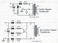
I'm using a Triad VPT230-110 as the B+ supply for an Aikido all-in-one line stage. I'm running the transformer in series, red to orange jumped together, and the power supply in full-wave bridge configuration. I am regulating my AC input to 115V with a variac.
When I connect the transformer to the board, it buzzes, and rapidly heats up. Within a minute it becomes too hot to hold comfortably, and I dare not run it longer. With the leads disconnected, I measure 260VAC between the two leads, which is higher than the expected 230VAC. The transformer does not buzz or heat when disconnected from the board. When connected, the B+ voltage rises quickly to ~340VDC, then begins to decrease. I haven't been able to observe a stabilization point, because I am afraid to run the transformer that long.
The 12v heater power supply and transformer function as expected. All tests were done with both transformers connected and tubes installed. I have carefully examined the B+ power supply circuit for errors are defective parts, but have found no problems. I have ordered replacements so that I can rebuild the supply if necessary.
I observe a ground voltage potential of ~70VAC when the ground is floated. Swapping the input leads reduced this to ~25VAC, but did not improve the behavior.
I'm at a loss as how to proceed.
Attachments
A transformer with no load gives a slight higher Voltage.With the leads disconnected, I measure 260VAC between the two leads,
From the datasheet:
Output Voltage: Series: 230VAC CT @ 0.11A
Are You sure the tubes don't need more than 100 mA ?
Bear in mind You should also have some safety margin, so probably You can only go up to 75mA.
The spec given in the manual is 90mA, which is already a margin against the actual specified draw of 50mA.
Will measuring between the leads when connected give an accurate reading?
Will measuring between the leads when connected give an accurate reading?
Try loading the composite transformer secondary only with a power resistor, rated at 2k at 25W.
You can use two series 1k 20W power resistors. If there's no problem then, it must be the circuit.
You can use two series 1k 20W power resistors. If there's no problem then, it must be the circuit.
The voltage between the centre tap and ground is indeterminate because the transformer secondary winging is floating, so the 75Vac or 25Vac readings don't mean much.
A transformer that is mechanically vibrating and heating rapidly usually indicates the secondary is effectively short circuited. Something on your board is likely causing excessive current draw. This behaviour can also be caused by shorted turns (i.e. insulation breakdown) inside the transformer, but if that were the case it would overheat when not connected, so the problem must be on your board not in the transformer.
A transformer that is mechanically vibrating and heating rapidly usually indicates the secondary is effectively short circuited. Something on your board is likely causing excessive current draw. This behaviour can also be caused by shorted turns (i.e. insulation breakdown) inside the transformer, but if that were the case it would overheat when not connected, so the problem must be on your board not in the transformer.
You'd need a current probe for that. Or else add a small series resistor and measure the voltage across it,What point should I measure across to observe current draw by the circuit?
which could affect the operation of the circuit somewhat. I suspect the transformer is ok, and the board is at fault.
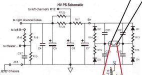
I unsoldered one leg of R17 (see attached, ignore annotations) and connected my multimeter between the floating leg and the hole. I measured ~340VDC and 125mA. I did the same for each of the AC connections from the transformer, and got 67mA on each.
Assuming this is a valid test, 75mA higher than spec
Assuming this is a valid test, 75mA higher than spec
Attachments
I ran the transformer across a 5000 ohm 20W resistor (it's what I had). It didn't buzz or heat up.
Last edited:
I did, but it's been fixed now. Not sure if those caps were damaged in some way? They read fine, and they look fine. I have two more on order regardless. I'll recheck for any others, but I'm pretty sure the rest are correct.Have you got a filter capacitor in backwards somewhere?
A transformer with no load gives a slight higher Voltage.
From the datasheet:
Output Voltage: Series: 230VAC CT @ 0.11A
Are You sure the tubes don't need more than 100 mA ?
Bear in mind You should also have some safety margin, so probably You can only go up to 75mA.
this is absolutely true, when you measure the no lad voltages with a dmm, the load is the input impedance of your meter which in this case can go as high as 10 meg per volt...now as you load your traffo the terminal voltages naturally comes down when current flows in the dc resistance of the winding ad some voltages are lost as a result...
I ran the transformer across a 5000 ohm 20W resistor (it's what I had). It didn't buzz or heat up.
this is a good practice, i also use dummy loads to find out how low the dc voltages go, and then adjust the dropping resistors as you go down the line...
I think I may have found the culprit. I removed all of the capacitors from the filter network (C19-C22), and the buzzing stopped. I checked them, and one had zero resistance across it's legs (other three tested OL). I reinstalled just the one with zero resistance, and the buzzing returned. I removed it, and installed one of the others in the same (arbitrarily chosen) position. No buzzing.
I have replacements arriving in a few days. In the mean time, the circuit should work without those capacitors, right? Just with less power filtering?
I have replacements arriving in a few days. In the mean time, the circuit should work without those capacitors, right? Just with less power filtering?

Good work.I think I may have found the culprit. I removed all of the capacitors from the filter network (C19-C22), and the buzzing stopped. I checked them, and one had zero resistance across it's legs (other three tested OL). I reinstalled just the one with zero resistance, and the buzzing returned. I removed it, and installed one of the others in the same (arbitrarily chosen) position. No buzzing.
good job.......buzzing is a sure sign of saturating traffo, best to avoid at all cost..
- Home
- Amplifiers
- Power Supplies
- Transformer buzzing and heating up