First of all I'm going to say that I'm a newbie to electronics, so this could all be a load of rubbish, but I had an idea...
Why not use a transformer to derive the "error signal" between the input and the output of an amp? If you connected the signal to the top of the primary winding of a 1:1 transformer, and the output to the bottom, wouldn't you have an error signal on the secondary which could be used for feedback? Any advantages to doing this or is it stupid?
Why not use a transformer to derive the "error signal" between the input and the output of an amp? If you connected the signal to the top of the primary winding of a 1:1 transformer, and the output to the bottom, wouldn't you have an error signal on the secondary which could be used for feedback? Any advantages to doing this or is it stupid?
Transformer coupled feedback was done in tranformer-coupled transistor push-pull amps for instance. Nowadays these are obsolete.
RF amplifiers is the place where transformer-coupled transistor amps have their merits (and where they are still used nowadays). Some of them actually use transformer-coupled NFB.
Regards
Charles
RF amplifiers is the place where transformer-coupled transistor amps have their merits (and where they are still used nowadays). Some of them actually use transformer-coupled NFB.
Regards
Charles
bigwill said:First of all I'm going to say that I'm a newbie to electronics, so this could all be a load of rubbish, but I had an idea...
Why not use a transformer to derive the "error signal" between the input and the output of an amp?
Any advantages to doing this or is it stupid?
bigwill,
You have very good idea and not stupid.
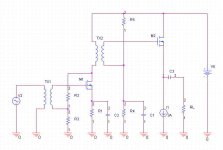
I built the prototype based on this idea.
Sound was very good!
But there is better topology for trans. coupled amp.
Attachments
I don't say it's stupid more like no insight of the problem you want to solve.bigwill said:Any advantages to doing this or is it stupid?
If you don't take into account that the transformer is unlinear (create distortion) and you don't need any galvanic insulation, what other possible advantage would this transformer create? You must always try to state the pros and cons when you have an idea. I admit though that this is hard when you haven't got enough of knowledge.
rozak said:In principle it is not good idia include trans in feedback loop
because of phase shift. If You must use secondary.
I guess
") It might work if you used it within the areas of the transformer's minimal phase shift though...
It might work if you used it within the areas of the transformer's minimal phase shift though...rozak said:peranders,
1 transistor transformer coupled and loaded VAS sounds better
then "0" distortion OPAMP for me at least.
This is what all diyers looking for?
It's good but it's not good?rozak said:In principle it is not good idia include trans in feedback loop
because of phase shift. If You must use secondary.
 can't say I'll understand you here.
This technique has never(?) been seen in high-end, not in really weird high-end, not in normal products even so I have even more serious doubts what good it can bring.
I don't see any advantage to this at all. Seems to me that feedback would be better and more simply implemented in the form of a source resistor.
However...
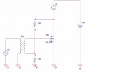
Looking at the feedback voltage divider with the bottom of the secondary tied to the node between the two resistors, I'm thinking if you take R1 and tie it to V+ instead of the MOSFET's drain, now you can bias the MOSFET without having to cap couple the input to prevent DC current from flowing in the transformer's secondary.
Something like tihs:
Or if you really like the taste of iron, a little MOSFET parafeed.
se
However...
Looking at the feedback voltage divider with the bottom of the secondary tied to the node between the two resistors, I'm thinking if you take R1 and tie it to V+ instead of the MOSFET's drain, now you can bias the MOSFET without having to cap couple the input to prevent DC current from flowing in the transformer's secondary.
Something like tihs:
An externally hosted image should be here but it was not working when we last tested it.
Or if you really like the taste of iron, a little MOSFET parafeed.
An externally hosted image should be here but it was not working when we last tested it.
se
Hi bigwill
It could be workable and there is nothing thechnically wrong with your idea.
However:
This way you will have no (open loop) voltage gain. using follower as output stage neither gives voltage gain. So there is virtually no feedback.
Better to have transformer with voltage gain (not 1:1) or voltage gain active part. Than you get local feedback power follower. Probably 15-20dB will be max. feedback without risk of oscillation for a circuit with a transformer within feedback loop.
What is controversial is a philosophy beyond such circut. Most retro/passive/simplicity lovers are rather also feedback haters. But I don't want to talk about philosophy here.
It could be workable and there is nothing thechnically wrong with your idea.
However:
bigwill said:If you connected the signal to the top of the primary winding of a 1:1 transformer, and the output to the bottom, wouldn't you have an error signal on the secondary which could be used for feedback?
This way you will have no (open loop) voltage gain. using follower as output stage neither gives voltage gain. So there is virtually no feedback.
Better to have transformer with voltage gain (not 1:1) or voltage gain active part. Than you get local feedback power follower. Probably 15-20dB will be max. feedback without risk of oscillation for a circuit with a transformer within feedback loop.
What is controversial is a philosophy beyond such circut. Most retro/passive/simplicity lovers are rather also feedback haters. But I don't want to talk about philosophy here.
bigwill said:How about something like this? (See attachment, excuse the poor drawing
This way you can get (closed loop) voltage gain, so it can no longer be power follower, but power amplifier. I thought you'd meant no center tap to ground.
darkfenriz said:
This way you can get (closed loop) voltage gain, so it can no longer be power follower, but power amplifier. I thought you'd meant no center tap to ground.
My original idea was to not have the center tap, but for some reason I drew one in on that schematic. (I thought it would be more likely to work, or something
 )
)
Steve,
You can see my actual topology in
http://www.diyaudio.com/forums/show...&threadid=56808
Peranders,
This technique has never(?) been seen in high-end, but who cares?
I'm crasy diyer and I like to build crazy amps and they
suddenly sounds better then some "normal".
I have no doubts ther is many trasformerless amps better than my ugly amp, but I can't find the trick.
- Status
- This old topic is closed. If you want to reopen this topic, contact a moderator using the "Report Post" button.
- Home
- Amplifiers
- Solid State
- Transformer based feedback?