I hope Bud or one of the guys who knows transformers in depth can (and is willing to) answer a really strange question.
I wanat to take a Variac and drive a 18Vrms transformer that has an isolation specification of 2KV or better.
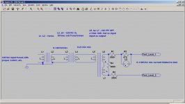
Since the Variac goes from 0 to 140V, I now have a 0-21 Vrms output at 60Hz.
Apply the output to the 4 ohm output terminals of a 10W audio transformer with 2KV or better isolation that rated from 20Hz to 20KHz with 10K p-p output.
The P-P Input leads (center isolated) have a resistor string equal to a 2KV rating at 500K ohms.
In addition each lead feeds a 250K resistor string with a 1KV or better rating. One lead also has a 47K resistor in series to a test lead. Across the 47K resistor is a NE51 whose turn on is 90V.
The other string of resistors has a test lead attached.
Is this safe? Aside from the fact that I'm going to generate over 1KVrms and I need to take appropriate cautions.
Will the audio transformer hold up and transform the voltages as calculated?
Will there be no core saturation since I'm at 2W dissipation with the two test leads floating and 4W dissipation with them shorted?
Thanks.
I wanat to take a Variac and drive a 18Vrms transformer that has an isolation specification of 2KV or better.
Since the Variac goes from 0 to 140V, I now have a 0-21 Vrms output at 60Hz.
Apply the output to the 4 ohm output terminals of a 10W audio transformer with 2KV or better isolation that rated from 20Hz to 20KHz with 10K p-p output.
The P-P Input leads (center isolated) have a resistor string equal to a 2KV rating at 500K ohms.
In addition each lead feeds a 250K resistor string with a 1KV or better rating. One lead also has a 47K resistor in series to a test lead. Across the 47K resistor is a NE51 whose turn on is 90V.
The other string of resistors has a test lead attached.
Is this safe? Aside from the fact that I'm going to generate over 1KVrms and I need to take appropriate cautions.
Will the audio transformer hold up and transform the voltages as calculated?
Will there be no core saturation since I'm at 2W dissipation with the two test leads floating and 4W dissipation with them shorted?
Thanks.
I think this might be interesting, but your description confuses me. Is there a possibility of drawing a (crude) schematic of this? I'd like to see where this goes.
Third try, I keep getting Security Token Errors. Attachment is 69.2KB
Attachments
Last edited:
As long as the primary of the OPT is rated for 1100 V I would think the circuit in the schematic would work. Note, though, that the primary of the OPT needs to be designed for operation at 1100 V RMS. It's not enough that the dielectric strength between primary and secondary is designed for 1100 V.
Proceed at your own risk!
~Tom
Proceed at your own risk!
~Tom
It may not be safe for your OPT - you may break down the insulation wiring within the primary, as the voltage across the PP primary may not be rated for 2kV I suggest.
The isolation from pri to sec or to core may be rated/ok for 2kV, but that may be for different insulation within the OPT.
Measuring floating voltages can be more hazardous than if say the OPT CT was earthed - depending on your meter or if a fault occurs.
Ciao, Tim
The isolation from pri to sec or to core may be rated/ok for 2kV, but that may be for different insulation within the OPT.
Measuring floating voltages can be more hazardous than if say the OPT CT was earthed - depending on your meter or if a fault occurs.
Ciao, Tim
The OT will come close to smoke, but may squeak by, if you put 21 Volts RMS on the 4 Ohm winding.
Watts = Vrms*Vrms/R
or Vrms = Sqrt(R*Watts) = Sqrt(40) = 6.32 Volts. That would be at the low frequency spec for the OT. Assuming that is 20 Hz, then you can get away with 3 times that voltage at 60 Hz. So 3* 6.32 = 18.96 Volts at 60 Hz. Saturation will set in somewhere above 18.96 Volts, depending on design, and the current will then skyrocket. (Guitar OTs generally have a higher low freq. spec, more like 40 Hz, and cheap OTs in general may be Watt rated right at saturation.) You will have to listen to the OT to see if it starts humming badly suddenly near 21 Volts.
Last edited:
Third try, I keep getting Security Token Errors. Attachment is 69.2KB
Next time don't use JPEG format for storing screenshots and you won't have any problems.
JPEG format takes advantage of certain facts pertaining to photos and is pretty much useless for images that contain large areas of a single color (as you can see for yourself - your image looks "smeared" even though the screenshot looked just fine in your image editing program up until the moment you saved it).
Losless compression is far more suitable for such images and usually produces smaller image to boot. PNG is the format of choice for screenshots. Try to make JPEG and PNG of the same screen capture and compare them side by side - you'll immediately notice the horrible artifacts JPEG produces. Stick with JPEG for photos 😉
Thanks Arnulf, I'll use PNG next time.
Smoking-amp, I was thinking of Hammond or Edcor transformers. So they may have a chance. Given 1100V out at 4mA the output of the 18V transformer should be around .21A. I'll put a .5A fast blow fuse in that point in addition to the normal fuse on the input of the Variac.
The .5A fuse won't protect the OPT, but if it does go Ka-Put the fuse will keep the fault from cascading back into the 18V transformer and Variac.
I'll put a .5A fast blow fuse in that point
You can use a fuse in the final design, but do your testing with a 12 volt bulb from a car (tail or brake light). THe bulb can eat all 21 volts for a while (it will be bright) and should make everything nearly blow proof. If the transformer saturates the bulb lights up, no big deal.
- Status
- Not open for further replies.
- Home
- Amplifiers
- Tubes / Valves
- Transformer abuse or other use