At last I have a successfull experiment 😀
I like transconductance amplifiers (high output impedance) and I like the Aleph J, and so of course I wanted to combine the two!
My thought process was:
And in the end it worked perfectly. I get the same distortion spectrum as a normal Aleph J, same-ish output power and most importantly ~ 120 ohm output impedance instead of the 0.4 ohms of the real Aleph J.
And an additional note: With a single sided supply we need the voltage feedback loop. Without it the current feedback makes the amp oscillate. Amplifier topologies for current-drive | Current-Drive - The Natural Way of Loudspeaker Operation explains this.
I like transconductance amplifiers (high output impedance) and I like the Aleph J, and so of course I wanted to combine the two!
My thought process was:
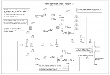
- Start with a normal Aleph J
- Convert it to use a single sided supply because that is what I have: I added R51-R55 to a normal Aleph J and omitted R2.
- Reduce voltage feedback by X: In the end upping R4 by 4x to 820k reduced this by ~ 12 dB.
- Wrap a current feedback loop around it for ~ 12 db of current feedback and connect it to the negative input. Here I reduced R3 to let me use a smaller current feedback resistor in series with the speaker to waste less output power.
- Get the result of an Aleph J with same distortion spectrum but with high output impedance, a current source amplifier like the F1 and the F2 without impedance reducing resistors.
And in the end it worked perfectly. I get the same distortion spectrum as a normal Aleph J, same-ish output power and most importantly ~ 120 ohm output impedance instead of the 0.4 ohms of the real Aleph J.
And an additional note: With a single sided supply we need the voltage feedback loop. Without it the current feedback makes the amp oscillate. Amplifier topologies for current-drive | Current-Drive - The Natural Way of Loudspeaker Operation explains this.
Attachments
OllBoll, interesting, so the same harmonics. Did you measure them with speaker, or test resistor? How about intermodulation distortion?
Btw, I got the same spectrum for transonductance chip amp vs normal application circuit, but sound was significantly better in current mode. Why?
Btw, I got the same spectrum for transonductance chip amp vs normal application circuit, but sound was significantly better in current mode. Why?
OllBoll, interesting, so the same harmonics. Did you measure them with speaker, or test resistor? How about intermodulation distortion?
Btw, I got the same spectrum for transonductance chip amp vs normal application circuit, but sound was significantly better in current mode. Why?
I measured with a resistor as speaker. With a real speaker I only listened. And listened without DSP to fix the response as it was just on the workbench. I haven't measured intermodulation distortion. Since it has nice and low harmonics I've just assumed that it will be good enough.
And of why sounding better depends on the speaker and how it is designed. If you correct the frequency response changes then current source amplifiers are great. The magic is that it can correct a lot of distortion in the actual driver. If you have a measurement microphone I suggest just doing a sine sweep with both configurations and look at the differences. I did a similar test 6 years ago comparing a Hypex NCore NC400 with a puny Choke loaded Zen. Parallelling voltage + current source amp with active crossove?. Above 2 octaves of fs the current source Zen has less distortion than an NC400, which is touted as having so low distortion you need high precision equipment just to measure it. But considering it in practical uses generates higher distortion in my speaker than my flea amp I went back to building flea amps.
In further detail: With a normal voltage source like the standard Aleph J amplifier amplifies such that the output voltage is the same as the input signal but bigger. The problem is that the impedance of a normal dynamic speaker varies over time, this creates distortion. The current is the same, however, so if we instead control the current then this specific distortion is just gone.
It is this impedance variation that most drivers reduce with big copper sleeves / rings in the motor. Super high quality drivers benefit less than cheaper drivers from using a current source as the impedance variations are less. Without the copper the driver can be made more efficient though, the 6ND430 for example performs gloriously with a current source amplifier. Exotic drivers like planars have a constant impedance though, they should perform the same driven by either a current source or a voltage source.
Hi OllBoll, thanks for the link, I will look at it. I use current amp only from ~150Hz, to power satelites (open baffle). And standard classAB for woofers. I compared standard chip amps (I prefer lm1875 to 3875 or 3886) with transconductance circuit. I have about six 1875 stereo transconductance amps with various power supplies, two stereo amps with 3875, and one with 3886. I am hoping to build F1 soon.
However, for listening tests I used the same power supply, only replaced the amp. I do equalize fr response absolutely flat with behringer ultracurve, after every change. I understand that resulting fr response difference in current drive would make difference on sound, hence I want to eliminate with eq in listening position (microphone exactly in same position, unmoved). Still I hear current amp being more musical. Since sine wave (1kHz only) is not showing much harmonic difference, I think its not representative of real music, being such a complex signal. My theory, although no data yet to support it, that in normal amp, feedback corrects all on the output, but amp does not care what happen next to the signal. Speaker, being so complex load causes some phase shifts. Current amp has possibility to correct for timing errors. Hence more musical presentation, including better transient response.
With application circuit, amp sounds clean, yet flat and boring. With current drive, its more dynamic. Correcting to flat fr response, this is not the difference. Finding harmonics similar on sine wave, this is not the difference. Perhaps other measurements would reveal what it going on. My theory is that better timing/phase/transients in current drive sounds better. I have no way to prove it. I just like it.
I've made some improvements:
R7' can be replaced by normal Aleph J resistor @ 1k, so R7. The bias is adjusted by R55 although R51 and R52 should probably be replaced with 210k, and R55 changed to 100k. Or just add some additiona resistance in series to R53 and R54.
The biggest improvement though is that I could reduce R3 from 2.2k to 390 which in turn increased the output impedance to 620. Keeping the same output power and distortion spectrum of course.
There is a bit of a turn-on and turn-off thump (I measured 4V thump) as usual with a capacitively coupled amp so while I consider the amp circuit complete I'll probably build a circuit to switch between the speaker and a 8 ohm resistor, to add a turn-on delay and to switch back when rail is lost. Mostly because I have already built an audio detect which turns on the amp, so it will turn on and off more than if switched manually.
Project 38 is the audio detect schematic I have built. I'll switch my 48VDC rail though and not the mains as i have an external AC -> 48VDC power brick.
Last edited:
Something like 10 years ago, I had a transconductance amp built for me. The output impedance is around 600 ohms measured and the power output is something like 100 watts.
The intent was to measure the THD difference between current drive and voltage drive.
The conclusion I reached was that there is a measurable difference but that the difference is small compared to how much THD is generated by the speaker when the speaker is driven at realistic listening levels.
The non-linear inductance of the voice coil creates enormous amounts of distortion in the voice coil current. If you want to see this, just place a small resistance shunt in the circuit, drive the speaker to large excursions at 15 Hz and place a scope across the shunt.
Changing from voltage drive to current drive shifts the distortion at the voice coil from the current domain to the voltage domain. A scope will show you this.
Hi OllBoll,
did you measure or calculate the output impedance to be 120 Ohm?
Measured. I'm not that good (yet) with circuit simulation in spice so I never simulated it before I tried it.
Also why I say 120 ohm ish (and later 600 ohm ish) as I don't have 1% tolerances on my resistor array as substitute for a speaker =)
- Home
- Amplifiers
- Pass Labs
- Transconductance converted Aleph J