My 1001st post at diyaudio should be special, and therefore I made it quite extensive!!
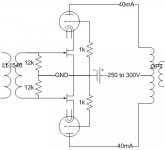
A couple of weeks ago I built a simple variation on the FirstWatt F2 amplifier (using IRF820’s as transconductance amplifiers and DN2540’s as CCS on top) to drive a pair of 150R headphones. I was really amazed by the sound quality compared to a single ended amplifier based on a 6N6P with a quite good output transformer (10k to 150R, amorphous core by AE-europe). The difference is probably due to the ‘transconductance’ aspect of the F2 which matches well with single drivers without crossovers (as headphones). So I started thinking about a transconductance amplifier based on tubes for a couple of Visaton B200 / Fostex FE206E fullrange drivers and the solution is, apparently, to use pentodes due to their high plate resistance (as explained in the RLD article by SY, for example), or maybe, I thought, (hybrid) cascodes! So I came up with the little schematic attached to this message: JFET’s as the bottom element, cascoded into triodes (I am thinking triode wired EL84’s here). Please bear with my ignorance regarding SS stuff, and help me with a couple of questions:
A first, general question regards biasing of the JFETS’s. I have seen quite some schematics of JFET based transconductance amplifiers in which the source is simply attached to ground (as well as the gate, through a resistor): so source and gate are at the same potential and my gut feeling says it would clip like crazy (at least it would with tubes in class1: therefore they are biased in a way that under the imposed AC swing the grid remains negative in relation to the cathode and doesn’t pull current). In my F2 ‘clone’ I also connected source to GND (and biased the grid positive) and apparently it works nice! I have also had a look at the vacuumstate cascode schematics, and they have a resistor in series with the source. I read (tubecad) that the use of a resistor in the source decreases transconductance of the (J)FET and therefore also the overall gain of the stage (as gain is ~ transconductance * Rload). Question is: can I just connect the JFET as in the schematic?
Related to this questions is the amount of current a JFET can handle: I have a couple of J310’s and therefore looked at their datasheet. Tubes use to have a value for maximum ‘cathode current’ and mosfet’s for ‘source current’, but for these JFET’s I have only found a maximum value of 10mA for the ‘forward gate current’. Furthermore I have found that the Idss value of a J310 is between 24mA and 60mA. Therefore I thought to measure up my stash of them, looking for a pair with Idss of 40mA…but, can they handle it, and second, Idss is measured with source and gate to ground, and I don’t know if the overall concept will work with this connection (see question above). With about 250 to 280V from anode to cathode and 40mA standing current the EL84’s will bias at about 10V, which is the Vds over the JFET’s: if they pass 40mA each the dissipated heat will be about 400mW, which is within the J310 TO92 ratings (but I could also use other JFET’s in parallel to reach 40mA total current).
And what about the gain of this circuit – can I use it for anything more than background music (or maybe not even that…) ?
For the rest there is not much I can say about it. Input is a LL1540 with two 12k resistors as recommend per datasheet. I know that output transformers work best if fed from a low source impedance, but that is a voltage amplifier: Transconductance amplifiers require high source impedance and hopefully a transformer works with it. I like the fact that only one PS is needed (transconductance amplifier with pentodes would need a screen supply and bias supply) and if the JFET idea works I will match them as tightly as possible to guarantee current balance in the output transformer even if the workhorses (EL84’s) get older…
Thanks for reading my post and for sharing your experience!
Attachments
Yes, JFETs are happy with Vgs = 0; this is the condition when you get IDss.
The only difficulty is that you want some current swing around this; ideally you want to be able to go between near zero current, and to about double the standing current. Reducing the current is no problem, negative gate voltages do that, but increasing it requires positive voltages; the gate channel diode will go into forward conduction at some point (about 0.7V), so there is only limited scope for positive inputs.
So for a large signal amplifier, I think you want to choose a bias point that is about 1/2 to 2/3 of IDss. The easiest way to do this just to stick a source resistor in, chosen so that it self biases to an appropriate Vgs. Looking at the spec sheet, something like -0.7V would be good, with say 20mA in the resistor, which comes at 35Ohms - 33 will be close enough.
If you want more than 20mA standing current, parallel up an extra pair.
I think you will have plenty of gain; about 1V rms will drive it close to full modulation.
Eric,
Biasing for JFETs is the "same" as for tubes. In a common source configuration, employ a RC network between the source and ground.
Be sure to watch the device dissipation. DEFINITELY use a heat sink when exceeding 50% of the allowable max.
Biasing for JFETs is the "same" as for tubes. In a common source configuration, employ a RC network between the source and ground.
Be sure to watch the device dissipation. DEFINITELY use a heat sink when exceeding 50% of the allowable max.
Hi Piglets Dad and Eli Duttman
Thanks for your answers. So a JFET is indeed a bit different than a tube, as it can go positive without the gate pulling current... but it only does so until 0,7V... In combination with Eli's recommendation on the dissipation of these JFET's I will indeed go for two J310 in parallel, each biased at around -0.7V. I think I can do it best by sticking a 33R resistor between source and gate, ground gate, and match the J310 for 20mA's (660mV over 33R resistor)?!
Many thanks!
Erik
Bias gate to ground through a resistor (the 12K in your schematic), or even use centre tapped winding, with CT at ground. 33 Ohm between each source and ground.
Resonable matching is good, but I wouldn't sweat about.
Local feedback from 33Ohm source resistors will improve linearity, but won't increase drive requirements too much. If you find you need more gain, you can bypass the source resistors, but you will need big capacitor values - say 220 or 470 uF. Personally, I would rather have the feedback but YMMV
Bias gate to ground through a resistor (the 12K in your schematic), or even use centre tapped winding, with CT at ground. 33 Ohm between each source and ground.
Resonable matching is good, but I wouldn't sweat about.
Local feedback from 33Ohm source resistors will improve linearity, but won't increase drive requirements too much. If you find you need more gain, you can bypass the source resistors, but you will need big capacitor values - say 220 or 470 uF. Personally, I would rather have the feedback but YMMV
My very recent experience with large electrolytics bypassing small value cathode (or source) bias resistors has been very bad. In all cases removing them has resulted in much better sound. Problems have included bursts of distortion, audible ringing, and smeared transient response. (As heard and viewed on scope) I've tried various commodity caps, Nichicon Muse, and several grades of Black Gates - unfortunately none were acceptable. The Black Gates were barely listenable resulting in badly smeared transients and poor rise times - the others were all intolerable. This was in the front end of my phono stage where the levels are quite low, but I would expect rather low levels in your headphone amplifier as well, and through them all warts will be stunningly audible.
You might want to check out 417A/5842 as a single stage high transconductance head phone driver (spud amp). Another possible candidate for a headphone amplifier would be the 5687. Consider keeping it very simple, just SE with a single tube, an excellent OPT, and a very quiet supply. Incidentally in these applications I run fixed bias because it removes the coloration imparted by the large electrolytic bypass caps required for cathode bias. My latest headphone amp uses a choke loaded 5842 to drive a 71A driving a 5K:32 or 8 ohm OPT (electra-print custom) and sounds pretty good imho. (The noise floor is below my FFT analyzer's noise floor it's shocklingly quiet.)
Last edited:
Not sure I have much to add about your design, but as you know I more or less accidentally built a single ended pentode based transconductance amp for Grado headphones. I've had some time to spend with it, and took it to a headphone meet for others to hear, and the consensus was that it is a really good amplifier. The basic sound characteristic is that it almost makes Grado phones sound like electrostatic phones. The sound is unnervingly clear and crisp and detailed, but also warm and full with exceptional bass.
I tried it with other phones, including some higher Z (300 ohms I think) phones and some low Z (30 ohm) orthodynamics, and the high Z's sounded terrible. The orthos were not quite terrible, but not quite good either (and they were very nice from a different amp of mine), but with Grados it was exceptional.
I am looking into something like a E55L based zero feedback spud transconductance amp for my fostex speakers, but I haven't gotten that far yet.
My first worry would be LF distortion because of the very high source impedance driving the transformer- probably significantly higher than a pentode. You might consider wrapping some feedback around the cascodes, maybe even adding a stage to provide some gain to throw away.
Hi PigletsDad
Thanks for the further explanation. I will start with plain 33R resistors as I like the idea of the increased linearity. Only if I need the extra gain I will have a look at decoupling of these resistors!
Kevin
Thanks for the suggestion! A couple of months ago I had the chance to buy a set of 10k to 150R OPT’s wound by a well known Dutch trafowinder. I made an adjustable PS (up to 300V) for B+ (capacitance multiplier based on a source follower) and two individual B- supplies with multiturn potentiometers for bias. Using some interchangeable boards in the rig I could wire in different tubes. The objective of the whole experiment was to get a grasp on the ‘sonics’ of each tube operated under different conditions. I tested triodes or triode-wired 6N6P, EL84, 6E6P, 6W6, 6Y6. Still have the D3a, E180F, 6S4S (the ‘said’ Russian similar for the 5814) and others to test. But then I put together the F2 clone and it actually sounded better than the above rig. Of course I may have made some mistakes in the rig (oscillations, etc) but that doesn’t take away the fact that the F2 clone made me hear things in the music I didn’t perceive before. In the near future I will go back to the rig above and include an adjustable regulated B+ for the screens and an adjustable regulated B- for the grids, to be able to test some pentodes and see if they can beat the F2 clone.
PS: my headphones are the HD590 by sennheiser bought about 10 years ago.
Dsavitsk
A couple of days ago I remembered your post on the 12HG7 amplifier and thought about asking your impressions after a couple of weeks. Seems it is not necessary anymore! Broskie once wrote about ‘current amplifiers’ for headphones, and showed the impedance curves for HD600’s (300R) and Grados (32R) headphones, and indeed the Grado’s were much flatter which would suit transconductance amplifiers better. Besides Broskie also wrote that in his experience the senns sounded best when fed from a low source impedance. Mine are the HD590 which are 150R and not very common (or maybe not high-end enough), but they sounded nice on the F2 clone, exactly in the way you describe: crisp, clear, but not fatiguing.
One question, though. Did you drive the 300R’s headphones straight from the 32R output of your amplifier? I am thinking about the mismatch of impedances, and if it may influence the sound. For proper loading on the secondary one could wire a resistor in parallel to the 300R, something like 39R, but that would reduce output impedance of the amplifier and some of the transconductance aspect would be gone…
SY
This is one of my worries to: if there is enough inductance on the transformers to allow LF to come through. Good matching of the JFET’s would allow current balance and some extra Henrys in the primary of the OPT. Furthermore, the idea is to use this amplifier after an active Xover (HP at 200Hz) with FR drivers (Visaton and Fostex), so maybe it works. And if it doesn’t, I will come back to ask (about) feedback!
My first worry would be LF distortion because of the very high source impedance driving the transformer- probably significantly higher than a pentode. You might consider wrapping some feedback around the cascodes, maybe even adding a stage to provide some gain to throw away.
hi SY
After the weekend in Leiden (where I drew up the above schematic) I am back home and had a look at what Morgan Jones has to say about cascodes, more specifically, the output impedance of a cascode stage. And: it is about the Ra of the lower valve (element) multiplied by the gain+1 of the upper valve. So, indeed, using JFET's as the lower elements will make for a very high output impedance. High output impedance is fine, but transformers ain't perfect: I am a bit less enthousiastic now, but will try it anyway tomorrow evening!
- Status
- Not open for further replies.
- Home
- Amplifiers
- Tubes / Valves
- Transconductance amplifier based on hybrid cascode