Hello!
My friend is rebuilt his Transcendent Sound Ground Grid power supply including the filament supply. He wants to know whether he can rewire the socket by using ECC99 rather than stock 12AU7.
The stock unit B+ and B- are 200v, is that ok remained the same voltage for the ECC99 in the same circuit??
Thanks!
Last edited by a moderator:
Hello!
My friend is rebuilt his Transcendent Sound Ground Grid power supply including the filament supply. He wants to know whether he can rewire the socket by using ECC99 rather than stock 12AU7.
The stock unit B+ and B- are 200v, is that ok remained the same voltage for the ECC99 in the same circuit??
Thanks!
Escentialy, the heater. 12AU7 uses 4 and 5, and 9. ECC88 has at pin 9, an internal shield to be grounded. That isn't a problem. The true problem is that ECC89 almost quadruply the gm of 12AU7 (about 3mS vs 12mS, then you must re-bias the set too.
Attachments
Last edited:
Compare the heater current. You might have to adjust something with the ECC99 as some psu in TS amps (GG, phono, SE-OTL) run at their max and transformers get very hot. I think the ECC99 needs a bit more current?
A lot more. At 12.6 volt, 12AU7 -> 150 mA, ECC99 -> 400 mA, which is most likely too much for the transformer and regulator (3 valves). Also, I wouldn't recommend running the ECC99 at such a low anode current (2 mA). The advantage it has over the 12AU7 (mainly much lower rp) only comes into play at >= 10 mA. However, the entire power supply circuit won't be able to deliver the necessary current(s).Compare the heater current. You might have to adjust something with the ECC99 as some psu in TS amps (GG, phono, SE-OTL) run at their max and transformers get very hot. I think the ECC99 needs a bit more current?
Last edited:
One thing I forgot to mention at the very beginning, my fiend will have new transformers installed. The secondary winding of each transformer will have 9v @1A on each transformer for the filament.
Transformer A and transformer B for B+ (for left channel and right channel respectively) share the same parameter on secondary winding as
- 225v @0.15A
- 9v @1A
Transformer C (for negative of both channels)
- 225v @0.15A
- 225v @0.15v
- 9v@1A
He wants to have 2 separate transformers for the negative rail but not enough space inside the chassis.
Thx!
A lot more. At 12.6 volt, 12AU7 -> 150 mA, ECC99 -> 400 mA, which is most likely too much for the transformer and regulator (3 valves). Also, I wouldn't recommend running the ECC99 at such a low anode current (2 mA). The advantage it has over the 12AU7 (mainly much lower rp) only comes into play at >= 10 mA. However, the entire power supply circuit won't be able to deliver the necessary current(s).
If not what about 12BH7 or 6GU7 instead of ECC99??
12BH7 will have basically the same power supply problems. A little less heater current but still twice compared to a 12AU7.If not what about 12BH7 or 6GU7 instead of ECC99??
6GU7 only runs with 6.3 V.
By the way, you can check out the valve data yourself:
Electron Tube Data sheets
Here is a nice guide from Hammond for calculating transformers and rectifiers:
Attachments
Last edited:
12BH7 will have basically the same power supply problems. A little less heater current but still twice compared to a 12AU7.
6GU7 only runs with 6.3 V.
By the way, you can check out the valve data yourself:
Electron Tube Data sheets
Here is a nice guide from Hammond for calculating transformers and rectifiers:
Thanks for the Hammond Guide.
Felip
> - 225v @0.15A
> - 225v @0.15A
> - 225v @0.15v
Idle current is 2mA per side, 4mA per channel, 8mA for the whole stereo rig.
Even allowing 5-20mA for regulator waste, 150mA windings seem excessive.
OK, the proposed tube is somewhat fatter. Still hard to imagine anywhere near the proposed PT spec.
Separate neg rails seems odd, because the long-tail resistors against the diff-pair cathodes gives very excellent PSRR on the negative side. Positive PSRR may be the greater "problem", since the SRPP is bolted to B+ and can do odd things when that is not steady. Personally I'd throw 100uFd on and call it good... 100K of stacked tubes can't swing much audio-range against a 100u cap.
___________________________
> a nice guide from Hammond for calculating transformers and rectifiers
That page has several errors.
I asked Hammond. They took the page "from the web" and are not inclined to discuss application details, they just wind them.
The half-wave choke-input answer is just wrong. Several others seem sloppy. Don't bet your iron on these numbers.
Hm, I'll have to dig out my old books and compare.That page has several errors.
I asked Hammond. They took the page "from the web" and are not inclined to discuss application details, they just wind them.
The half-wave choke-input answer is just wrong. Several others seem sloppy. Don't bet your iron on these numbers.
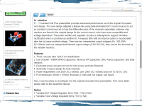
Actually Analogmetric has offered a kit with slight modification based on the Transcendent Sound Grounded Grid, and it states very clear about all parameters on their website.
The power requirement is 200v@100ma, so 0.15A is pretty safe.
The power requirement is 200v@100ma, so 0.15A is pretty safe.
Attachments
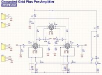
If that schematic is close to the Transc then the current is only 7mA at 2x 200volts (a plus and a minus 200v).Actually Analogmetric has offered a kit with slight modification based on the Transcendent Sound Grounded Grid, and it states very clear about all parameters on their website.
The power requirement is 200v@100ma, so 0.15A is pretty safe.
Changing the 12AU7 by other tubes will upset the hole DC situation and is very bad for the headroom for the AC signals.
Mona
If that schematic is close to the Transc then the current is only 7mA at 2x 200volts (a plus and a minus 200v).
Changing the 12AU7 by other tubes will upset the hole DC situation and is very bad for the headroom for the AC signals.
Mona
What about 12BH7? Will 12BH7 also upset the hole DC situation??
Dear Mona,
Can we use a very quality series HV regulator for the positive rail and have the SSHV2 for the negative rail?
This means 2 different type regulator for the positive and negative.
Again, still don't really get how to wire the SSHV2 for the negative rail for 200v B- regulation.
Thanks!
Can we use a very quality series HV regulator for the positive rail and have the SSHV2 for the negative rail?
This means 2 different type regulator for the positive and negative.
Again, still don't really get how to wire the SSHV2 for the negative rail for 200v B- regulation.
Thanks!
The 12BH7 is not that different, you could try it.
Mona
Keep it simple, rectify the 225volts (1fase positive, 1 negative or 2fase if you use two 225volts windings), gives round 300volts DC (+ and -) on a pair of electrolytics (~47µF).After that 10k (3W) for a drop of 100volts at 10mA, 7mA for the amp and 3mA for a zener shunt (take two zeners 100volts in series).On the amp decoupling C's if not allready there.
Negative side is a mirror of this.
Mona
Negative side is a mirror of this.
Mona
Strange that the 'improved' kit uses branded resistors, yet fails to reduce the values of R9-12 in order to reduce thermal noise. Maybe they didn't think it was worth doing as R3 and R4 are large too.
With a gain of 6x it is probably not intended for weak signals.Strange that the 'improved' kit uses branded resistors, yet fails to reduce the values of R9-12 in order to reduce thermal noise. Maybe they didn't think it was worth doing as R3 and R4 are large too.
And if you make R9-12 smaller the load resistance can't go less low.
In the meantime I amused myself by drawing a simpler version without the -200volts and some more current 😀.
Mona
Attachments

- Status
- Not open for further replies.
- Home
- Amplifiers
- Tubes / Valves
- Transcendent Sound Ground Grid