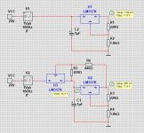
I want to build this circuit. My question is, are the two protection diodes no longer needed?
Thank you in advance for your answers.

Thank you in advance for your answers.
Diodes are necessary for to discharge capacitances. To prevent from backwards currents.
I think you should at least use 2 diodes. From output to input on both LM317.
I think you should at least use 2 diodes. From output to input on both LM317.
Genuine question: What's the point of this circuit - apart from spreading the heat dissipation across two regulator packages?
That would probably be alright.I think that would be enough.
I saw a simulation of this circuit and it looks very good.
View attachment 1427728
It will protect the LM317
Yes.
Add a signal on the input voltage. 100Hz or 1kHz.
Then check how much of this signal is on output.
First running with only one LM317.
Then do the same with two LM317.
And see what is the output difference.
Add a signal on the input voltage. 100Hz or 1kHz.
Then check how much of this signal is on output.
First running with only one LM317.
Then do the same with two LM317.
And see what is the output difference.
@Julian RO
Here I did a test.
First result was 1.84mVp-p
Two LM317 was 561nVp-p
That is a good improvement. Many decibel. Actually -70dB

Here I did a test.
First result was 1.84mVp-p
Two LM317 was 561nVp-p
That is a good improvement. Many decibel. Actually -70dB

Last edited:
You can improve the noise performance of this tracking pre-reg circuit by replacing R2 with a red or green LED. It is also a good idea to use a cap at C2 with some ESR a bog standard moderate ESR electrolytic would be good.
More info on this is in the section titled "using 3-pin regulators, Part 4" here...http://www.acoustica.org.uk/ (All due credit to Martin of course)
More info on this is in the section titled "using 3-pin regulators, Part 4" here...http://www.acoustica.org.uk/ (All due credit to Martin of course)
You would be well advised to use the remote 0v sense capability of the voltage setting LM317 unless you are using tiny load currents. You will get the most out of the 317 that way. Details are in the datasheet.
What this means is having three outputs, a +ve, a power 0v and a load sense 0v. The power 0v and 0v sense output leads join at the load negative. On your board you therefore would need a third (low power) connection from the 0v end of C4 and R6 in this schematic of yours below for the 0v sense. You really want to run these three output leads close together so a three way terminal block would be best.
Caps C2, C3 and C4 need to have moderate ESR to avoid instability and noise gain. I suggest 10uF electrolytics with an ESR of approx 0.1 Ohm. The more capacitance the lower the ESR needed. There's more detail on this in the LM317 pages of Martin's site linked to earlier. Don't use low value film caps here. The difference can be measured and will spoil an otherwise sound circuit.
John
I built one about 30 years ago but with no schematic, just using the datasheet. I have built the ALWSR many times and this is a Jung style super-reg fitted with an optional LM317 tracking pre regulator. When I have built this I have used LED(s) rather than R2, like this in the top diagram...

- Home
- Amplifiers
- Power Supplies
- Tracking preregulator circuit LM317