This is the positive half of tracking power supply. It represent a buck converter with voltage control mode.
U4 is integrator of square wave 600kHz, resulting in triangle wave with 5.6 v pp.
U3 is error amplifier, with 2 pole and 2 zero compensation network (R12, R11, C15, C14, C35, C14).
R14 determine the amplification of input signal (A=R11/R14=15). R48, conected at -15v introduces a offset in output, coresponding +7.2v at idle (Vcc x R11/R48=7.2v).
U5 is pwm comparator, feeding U1 fast optocuplor (6N137). Because the switching f=600kHz is high (for best transient response), Q12, Q13, M2, M3 form a buffer with sufficient current capability to drive M1 Mos Fet (IRFP260N).
L1, C5, C6, R3 is part of buck converter filter, with aprox impedance of 4.4 ohm.
Attachments
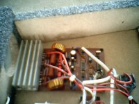
Good work
Ion,
This is something known as Class-TD[Lab Gruppen Style]
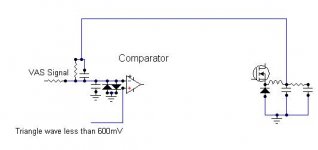
Have you tried the feedback directly into comparator, this will save you from lot of troubles arising from loop stability comprising error amp....[You have to change the phase also to implement it and also the amplitude of the triangle must be reduced to about 600mV to achieve high open loop gain]
regards,
Kanwar
Ion,
This is something known as Class-TD[Lab Gruppen Style]
Have you tried the feedback directly into comparator, this will save you from lot of troubles arising from loop stability comprising error amp....[You have to change the phase also to implement it and also the amplitude of the triangle must be reduced to about 600mV to achieve high open loop gain]
regards,
Kanwar
A link to Fredos post, explaining how to eliminate error amp...
http://www.diyaudio.com/forums/showthread.php?postid=1104977#post1104977
http://www.diyaudio.com/forums/showthread.php?postid=1104977#post1104977
Question
Feedback before or after LC? Because is ease in one way (before) but not compensating resonance of filter. Also the transient response is different.
Maybe is your turn to present some of your work.
Feedback before or after LC? Because is ease in one way (before) but not compensating resonance of filter. Also the transient response is different.
Maybe is your turn to present some of your work.
Re: Question
Feedback After Filter......Take a look at this.. example
ionutgaga said:Feedback before or after LC? Because is ease in one way (before) but not compensating resonance of filter. Also the transient response is different.
Maybe is your turn to present some of your work.
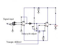
Feedback After Filter......Take a look at this.. example
Attachments
From my vision, the front end of monorail is too simple. Because RC input for speed-up high frequency interfere with absolute dc converter (non linear in+/-0.65v), because you sense output signal, not floating dc power.
Power disipation on class AB+tracking power, is P=7.5V * I(out), just because power final is polarised with aproxx 7.5 v, for normal operation (+/- ripple).
In monorail, power disipation it's double (2 * 7.5v * I(out)), just because H bridge...
Look at my proposed front-end (sensing diferential voltage, absolute value converter)...
I tryiet to simulate D1200 feedback in OrCAD: no positive result.
Any idea?
Regards,
Ion
Attachments
ionutgaga said:From my vision, the front end of monorail is too simple. Because RC input for speed-up high frequency interfere with absolute dc converter (non linear in+/-0.65v), because you sense output signal, not floating dc power.
Power disipation on class AB+tracking power, is P=7.5V * I(out), just because power final is polarised with aproxx 7.5 v, for normal operation (+/- ripple).
In monorail, power disipation it's double (2 * 7.5v * I(out)), just because H bridge...
Look at my proposed front-end (sensing diferential voltage, absolute value converter)...
I tryiet to simulate D1200 feedback in OrCAD: no positive result.
Any idea?
Regards,
Ion
Hi Ion,
I sense VAS signal not output....You absolute value converter takes care of small amplitude signals very well...
The power dissipation could be halved if polarised to 3.5V .....just same disspation as half bridge...but inturns you will get double the slew rate of half bridge....
I have not used Feedback in my monorail tracking amp, but i relied on Feedforward compensation by adjusting the amplitude of Triangular wave in proportion to power rail[not tracking, but the idle one] fluctuations....so simple....
What was your gain setting in sim....it had to be around 5X only...to get good results and manipulate the sensing signal also...to tally the pwm gain with amp gain....
Hi ION,
Have you got the schematics and Did you tried the direct feedback to comparator after filter and with gain of 5X...
Kanwar
Have you got the schematics and Did you tried the direct feedback to comparator after filter and with gain of 5X...
Kanwar
With gain=5 and +/-100vcc, seems like input is +/-20v. What about comparator? Is from discrete components?
The schematic in D1200 poweramp is ucd principle based. With forced clock or sync with clock, like in Philips audio systems. In my opinion, ofcourse. Correct me if i wrong.
The schematic in D1200 poweramp is ucd principle based. With forced clock or sync with clock, like in Philips audio systems. In my opinion, ofcourse. Correct me if i wrong.
ionutgaga said:With gain=5 and +/-100vcc, seems like input is +/-20v. What about comparator?
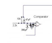
yes exactly, the triangle wave amplitude must be around 400mV and therefore the - input of comparator will not see more than 600mV due to inverse parallel diode connected to it....
The voltage at the - input terminal of comparator isnot going to see 20V in any circumstances....The comparator is LM319...
The class-d amps in which feedback is taken from after the filter seems to be a UCD to you.......😉
Are you shure?
Ucd is a power comparator selfoscillating. If you look at any service manual of Philips ucd power amp, you will see clock syncronizing in the similar minner, except summing of inv input.
Ucd is a power comparator selfoscillating. If you look at any service manual of Philips ucd power amp, you will see clock syncronizing in the similar minner, except summing of inv input.
ionutgaga said:Are you shure?
Shure is a reputed brand name for microphones, i am not Shure.....
- Status
- Not open for further replies.
- Home
- Amplifiers
- Class D
- Tracking power supply