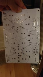
I'm making new boards for my f5 v2. Nothing special, I just added snubber, leds for +/- rails and two connectors for bleeder resistors for use only under testing. These will be removed when I plug the boards permanently. Also some testing points to make life easier.
The resistors of CRC filter are not seen because they'll be on separete boards connected vertically to save space.
Power in-out connectors are HDD type horizontally soldered. I got tired of terminal blocks with screws, but I am not yet sure what I'm going to use.
I started very seriously with this, but while placing traces, I started to draw instead of trace.....hehehe.... The rest of the work/playing will continue tomorrow. Got to get some sleep!
Anyway, any thoughts are welcome!
Last edited:
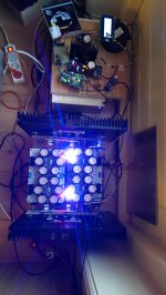
I don't see that, Andrew, after building these boards and attaching them to my f5. I can't see that on the cad file either. Of course what I posted is not the final design. The pic I posted was only for artistic purposes. It's my first try with curves and I'm very excited about that!
To close up the thread here you can see how it looks now fully built and integrated:
To close up the thread here you can see how it looks now fully built and integrated:
Attachments
- Status
- Not open for further replies.