Hello, new to the forum so sorry if this is wrong thread.
looking for advice as to how wide a trace should be for HP/LP Filter designs on 1oz. PCB.
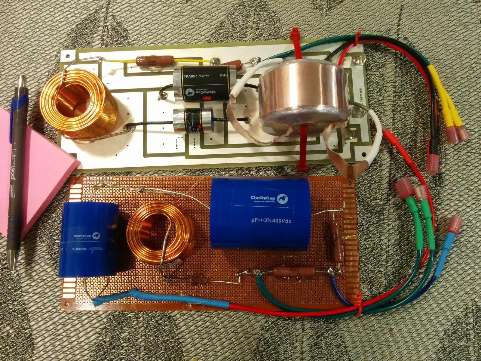
Using separate boards for HP/LP filters.
HP - 18Ga. Inductors and 250V Caps.
LP - 16Ga. Inductors and 400V Caps.
Currently the design has .125" traces.
I've looked at trace width calculators and don't know what I'm doing.
I based my design from the existing crossovers from the manufacturer.
Somehow I feel like I need to attend to this.
These Filters will feed Focal 8W woofer and ESS AMT5 Power ring in a bookshelf two-way.
Thanks.
looking for advice as to how wide a trace should be for HP/LP Filter designs on 1oz. PCB.
Can you post a schematic? You can use both sides of the pcb to double the copper thickness.
If the leads connecting to a node are soldered near each other, the width is less critical.
Last edited:
Hello, new to the forum so sorry if this is wrong thread.
looking for advice as to how wide a trace should be for HP/LP Filter designs on 1oz. PCB.
Using separate boards for HP/LP filters.
HP - 18Ga. Inductors and 250V Caps.
LP - 16Ga. Inductors and 400V Caps.
Currently the design has .125" traces.
I've looked at trace width calculators and don't know what I'm doing.
I based my design from the existing crossovers from the manufacturer.
Somehow I feel like I need to attend to this.
These Filters will feed Focal 8W woofer and ESS AMT5 Power ring in a bookshelf two-way.
Thanks.
Hi Baronski, generally as wide as you can make it. There is a trace width calculator built into this Android app.
BUT.... working with System7 (Steve) we've discovered some interesting interactions between the copper and inductors. There is measurable capacitive coupling and reduction of inductance when a large land appears under an inductor. It's rather surprising how thin it has to be to be measurable. I used to design my PCB's with giant copper areas. After this testing I've changed my mind.
Now I avoid copper lands under an inductor or large foil capacitor. This is counter to how a lot of commercial speaker PCB's are designed that try to use as much of the copper on the board as possible. It's not really needed. 1/4" traces will work for just about anything. I do think 0.125 is a wee bit thin, but probably not measurably worse.
If you want a more clear visualization, your trace calculators should provide you with mOhms of resistance. Plug them into something like XSim as resitors to examine the effects. XSim will also indirectly help you understand the currents flowing. Set the amplifier power to your maximum expected power and then look at the amperage per device. Then you can plug this current into the appropriate trace calculator. I'm pretty sure that if you do 0.250 traces you'll never notice it.
Last edited:
why PCB? - we are talking diy XO?
use perfbord if you like, hand wiring however should be a no-brainer
use perfbord if you like, hand wiring however should be a no-brainer
why PCB? - we are talking diy XO?
use perfbord if you like, hand wiring however should be a no-brainer
JCX Is right actually. 🙂 Also, tip from Sytem7, use wire tie anchors and hot glue to create mounting points for your expensive parts. This way you use wire ties for all the caps and coils, but hot glue never touches them. Makes it easier to remove them and re-use them later.
Best,
Erik
Thanks for all the reply's. I am wanting to try to fabricate my own pcb. looks simple and thought it would be more professional. The original crossover had many variations in large lands, with 1/8" traces leading to ground and common circuits. I have room to widen the traces, but want to make sure it is necessary. I might revise my design with 1/4" traces as advised, then re-evaluate. Looks like I have to upload photos via url, so maybe later on the schematic.
ax=copper ounces.
bx=current in amps
thickness in thou of inch = (1000 * (bx / ax)) / 66.6666;
It's the amps that are confusing to me. I plan to drive these with modest receiver. Power Amps and Receivers are not rated in Amps, so what am I missing?
Thanks for all the reply's. I am wanting to try to fabricate my own pcb. looks simple and thought it would be more professional. The original crossover had many variations in large lands, with 1/8" traces leading to ground and common circuits. I have room to widen the traces, but want to make sure it is necessary. I might revise my design with 1/4" traces as advised, then re-evaluate. Looks like I have to upload photos via url, so maybe later on the schematic.
I like doing that myself. 🙂 My one bit of advice though is you often end up tweaking a design for weeks after it's playing. Better to listen to it for a while before committing to a PCB.
Best,
Erik
It's the amps that are confusing to me. I plan to drive these with modest receiver. Power Amps and Receivers are not rated in Amps, so what am I missing?
Use XSim. Simulate your crossover, you can even use an "ideal" speaker driver. Set the Amplifier to 150 Watts, and open up the AddGraph menu. Select More --> Component Current
That will give you a great idea of current vs. f for each component. Select components in series with your traces and you'll know exactly how much will flow in the trace. 🙂 Since the current in the component must equal the current in the trace. A bit of a cheat, but a mathematically valid one.
Of course, you should also check the wattage of your resistors while using XSim. 🙂 It's most accurate if you have a ZMA file, but you can at least get a rough indicator this way.
Best,
Erik
Excellent advice on the moc-ups. I really should do this as my cabinet design allows for easy access to the boards. I've spent many hours evaluating the designs, but how they sound is the bottom line.
What suggestions do you have for Terminals? PCB terminals specifically.
Seems to be many available.
What suggestions do you have for Terminals? PCB terminals specifically.
Seems to be many available.
Excellent advice on the moc-ups. I really should do this as my cabinet design allows for easy access to the boards. I've spent many hours evaluating the designs, but how they sound is the bottom line.
What suggestions do you have for Terminals? PCB terminals specifically.
Seems to be many available.
Any tag or barrier strips will work. Personally I use pig tails with quick-disconnect terminals for everything, with crimp-on attachments. I can pull the tweeter or woofer board out fairly quickly, but that's not how most do it. 🙂
Some examples of good barrier strips:
From Parts Connexion
From Parts Connexion
An externally hosted image should be here but it was not working when we last tested it.
These were too hard to find, thank goodness for Google and image search. Of course there are other suppliers, but I only hang out at about 4 web sites, ever. 🙂
http://www.partsconnexion.com/product28870.html
But check out this droolicious use of the ceramic barrier strips
http://www.partsconnexion.com/product28870.html
An externally hosted image should be here but it was not working when we last tested it.
But check out this droolicious use of the ceramic barrier strips
Last edited:
The black cable ties are self adhesive, Erik. And easy enough to move around.
White Zip ties and 5 tag tagstrip there. Very easy to modify designs too, which is why I like this idea, partly borrowed from Troels Gravesen. I use 30 amp tinned copper wire for hookup. Fuse wire really, available at electrical wholesalers.
White Zip ties and 5 tag tagstrip there. Very easy to modify designs too, which is why I like this idea, partly borrowed from Troels Gravesen. I use 30 amp tinned copper wire for hookup. Fuse wire really, available at electrical wholesalers.
Any tag or barrier strips will work. Personally I use pig tails with quick-disconnect terminals for everything, with crimp-on attachments. I can pull the tweeter or woofer board out fairly quickly, but that's not how most do it. 🙂
Are those Mills resistors? One textbook I read recommended 50W minimum. But I chalked it down as typo. 12W OK?
Are those Mills resistors? One textbook I read recommended 50W minimum. But I chalked it down as typo. 12W OK?
They are indeed. You were right. 50W resistors is what you use to test amplifiers with. 🙂
Depends on the circuit and expected amplifier power. 🙂 That's what XSim is good for. Put your crossover in, and select your amplifier power, then open up the power window. Having said this, if you find it too tedious, 12W resistors will almost always work. Unless they don't.
Note I usually ascribe 20% of the power to the tweeter, 80% to the midwoofer. That is, if I expect a 100W Amp, I set the power to 20 W and examine the tweeter resistors. Then I set the power to 80W and examine the woofer resistors.
Make sure that in all cases the expected power < rated resistor power.
One of the 8 reasons I love Mills are the relatively small size compared to cement, and reason 5 that I love them is that for a top-tier resistor they are bottom of the price range.
Best,
Erik
Last edited:
FYI, I usually end up overrating my resistors. That is, the rated power is >> needed power rating. One advantage is they will just never wear out from thermal abuse. Another is higher power = lower noise. Not sure if it's at all audible though.
It's always safe to overrate your resistors, unless they are fuse-types and intended to blow at a certain dissipation. For crossovers these are never used. It's safe to put a 50W resistor where a 1 W resistor is called for. Not very useful, but safe. 🙂 At least keep a 20% safety margin when it comes to power. If your simulation says to expect 5W, then a 5W resistor is too small. Get at least 5 x 1.2 = 6W. I'd do 12, but overspending money for bigger resistors is proof of my manhood. 🙂
Erik
Last edited:
- Status
- Not open for further replies.
- Home
- Loudspeakers
- Multi-Way
- Trace path widths on PCB.