I was looking at this box since I have a few CHR-70v3s in addition to attempting to designing my first TQWT for another driver. I wanted to see how Hornresp would model the results of the DDVP-10-ML. I wanted a proven design to give me a baseline to better understand Hornresp so I can model my own ideas. Perhaps my numbers are off but the graphs do not show this box/driver combination to be a good match. Would anyone else be willing to take a stab at it and see how your results compare or offer a "sample" of a well-designed TQWT in Hornresp for the CHR-70v3 that I can use as a template? I listened to several "air recordings" available on Youtube like this and this and it sounded pretty good assuming it was well recorded and my B&W headphones were not failing me which was confusing compared to my modeled response. I don't have endless time and money to indefinitely try things so I am leaning on the modeling software to help- like everyone else! QW designs, Full Range systems, and Hornresp are all new to me, so thanks!
Last edited by a moderator:
Attachments
-
 Screenshot 2022-09-07 112918.png8.6 KB · Views: 495
 -
 Screenshot 2022-09-07 113548.png1.3 MB · Views: 648
 -
 Screenshot 2022-09-07 113510.png370.3 KB · Views: 584
 -
 Screenshot 2022-09-07 113428.png570.3 KB · Views: 1,206
 -
 Screenshot 2022-09-07 113320.png9.9 KB · Views: 583
 -
 Screenshot 2022-09-07 113144.png12.1 KB · Views: 441
 -
 Screenshot 2022-09-07 113110.png13.1 KB · Views: 352
 -
 Screenshot 2022-09-07 113029.png12.3 KB · Views: 429
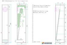
I am not an expert,
but as fas as I can see the dimensions in the drawing are not consistent with the parameters in Hornresp?
Knud
but as fas as I can see the dimensions in the drawing are not consistent with the parameters in Hornresp?
Knud
I don't doubt it at all. Trying to reverse engineer what Hornresp needs from a drawing is a stretch for me. I tried to derive the line length, the area at the beginning and end of the taper, the port dimensions, etc. I'm sure I have some of it messed up, especially right where the taper ends and the port begins. That's why I'm asking!I am not an expert,
but as fas as I can see the dimensions in the drawing are not consistent with the parameters in Hornresp?
Knud

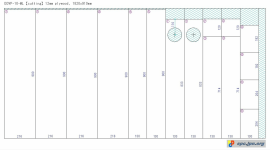
For example cut (3) plus circa half the distance from top of (3) to topplate - I think should be the first value of CON (714 +56 = 770)
S2 something like 13 * (11,1 -2,4) = 113,1
try and work on calculating the values for the rest of the dimension parameters. Unfortunately I have some sort of influenza 🤢 and the brain is running quite slow these days. This will also be be my excuse if I have misled you 😳
S2 something like 13 * (11,1 -2,4) = 113,1
try and work on calculating the values for the rest of the dimension parameters. Unfortunately I have some sort of influenza 🤢 and the brain is running quite slow these days. This will also be be my excuse if I have misled you 😳
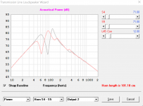
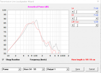
I got a better? plan; did a MLTL HR sim for this driver awhile back, so just used the Wizard to convert it to a conical (actually parabolic since there's at least one parallel wall set) and as I assumed it in theory requires more damping though doubtful anyone that doesn't have a sim to see the difference likely will never notice it.
Regardless, red is the ML-horn with NO added damping which will roll off the bass a bit.
Regardless, red is the ML-horn with NO added damping which will roll off the bass a bit.
Attachments
Re starting from scratch, easiest to calculate a T/S max flat alignment for at least a starting point (what mine are) and use Hornresp's Loudspeaker Wizard to 'slide' your way to an optimized sim for your app.
net volume (Vb) (L) = 20*Vas*Qts'^3.3
box tuning (Fb) (Hz) = 0.42*Fs*Qts'^-0.96
(Qts') = (Qts) + any added series resistance (Rs): http://www.mh-audio.nl/Calculators/newqts.html
net volume (Vb) (L) = 20*Vas*Qts'^3.3
box tuning (Fb) (Hz) = 0.42*Fs*Qts'^-0.96
(Qts') = (Qts) + any added series resistance (Rs): http://www.mh-audio.nl/Calculators/newqts.html
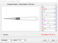
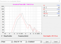
Is the graph marked Screenshot 2022-09-07 113029.png not what you are looking for?
No
dave
Thanks for all of this! I will mess with it tonight. The graphs look perfect. I’ll also look at what I can model using the same driver based on your starting place with the BR cabinets.I got a better? plan; did a MLTL HR sim for this driver awhile back, so just used the Wizard to convert it to a conical (actually parabolic since there's at least one parallel wall set) and as I assumed it in theory requires more damping though doubtful anyone that doesn't have a sim to see the difference likely will never notice it.
Regardless, red is the ML-horn with NO added damping which will roll off the bass a bit.
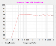
I see few mistakes in your sims in post #3.
First, Le entry is incorrect, way much bigger than it should be. Thats why HF rollof starts around 100Hz so graphs looks funny.
It should be 0,032mH. Type it like that and HR will round the figure to 0,03
Second, according to plans you posted S2 should be 113 sqcm. It looks like two sections dont have the same taper.
Also, vent is L-shaped so its longer, around 19-20cm across center line.
Finally, plans are showing less damping material than your sims, 30 grams below and 10 grams above driver.
HR will show you amount of stuffing in Loudspeaker Wizards Schematics window
I attached HR record file. You can unzip it and import it to HR and see the results.
Attachments
Thank you for the feedback. Those bits of course correction are very helpful. Also, thanks for the file!I see few mistakes in your sims in post #3.
First, Le entry is incorrect, way much bigger than it should be. Thats why HF rollof starts around 100Hz so graphs looks funny.
It should be 0,032mH. Type it like that and HR will round the figure to 0,03
Second, according to plans you posted S2 should be 113 sqcm. It looks like two sections dont have the same taper.
Also, vent is L-shaped so its longer, around 19-20cm across center line.
Finally, plans are showing less damping material than your sims, 30 grams below and 10 grams above driver.
HR will show you amount of stuffing in Loudspeaker Wizards Schematics window
I attached HR record file. You can unzip it and import it to HR and see the results.
Yes, it's going great.Is it possible to simulate in Hornresp TQWT with offset duct?
With the latest version.
- Home
- Loudspeakers
- Full Range
- TQWT design and Hornresp