Hi,
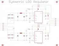
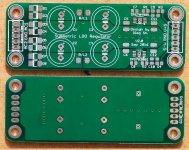
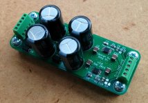
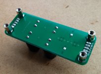
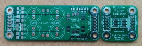
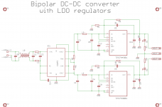
I offer bare PCBs for a bipolar PSU based on the TPS7A4901/TPS7A3001 low noise LDO regulators. It is capable of up to +150mA/-200mA current supply at +33/-33 VDC. The absolute maximum supply voltage to the board is 25 VAC (each rail) or +36/-36 VDC. The board size is 3x8 cm, mounting holes are on the 10 mm grid (2x7cm center-to-center distance). The design is briefly documented here. The schematic and images of the bare and assembled boards are attached.
PCB is hand solderable. The only challenge is soldering the thermal pads of the regulator ICs. It requires strong soldering iron to conduct the heat through the vias from the underside to the thermal pads. Using hot air rework station significantly simplifies the assembly.
The estimated BOM at Mouser is around 38 Euro.
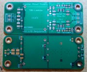
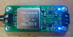
I also offer a new design board using DC-DC converter at the input (see post #10 for details and #11 for the BOM). The development thread is here. This board size is 3x7cm.
Price: 6 Euro/PCB (bare board, no parts)
Bipolar power splitter PCB: 2 Euro/PCB
Worldwide shipment: 2 Euro (ordinary mail) or 4 Euro (registered mail, traceable).
Payment by paypal.
PM if interested!
Regards,
Oleg
I offer bare PCBs for a bipolar PSU based on the TPS7A4901/TPS7A3001 low noise LDO regulators. It is capable of up to +150mA/-200mA current supply at +33/-33 VDC. The absolute maximum supply voltage to the board is 25 VAC (each rail) or +36/-36 VDC. The board size is 3x8 cm, mounting holes are on the 10 mm grid (2x7cm center-to-center distance). The design is briefly documented here. The schematic and images of the bare and assembled boards are attached.
PCB is hand solderable. The only challenge is soldering the thermal pads of the regulator ICs. It requires strong soldering iron to conduct the heat through the vias from the underside to the thermal pads. Using hot air rework station significantly simplifies the assembly.
The estimated BOM at Mouser is around 38 Euro.
I also offer a new design board using DC-DC converter at the input (see post #10 for details and #11 for the BOM). The development thread is here. This board size is 3x7cm.
Price: 6 Euro/PCB (bare board, no parts)
Bipolar power splitter PCB: 2 Euro/PCB
Worldwide shipment: 2 Euro (ordinary mail) or 4 Euro (registered mail, traceable).
Payment by paypal.
PM if interested!
Regards,
Oleg
Attachments
Last edited:
Hi OlegSh,
What's the output voltage and max output current? I guess the voltage is adjustable by changing some parts of the BoM?
Lastly, price to ship to Montreal, Canada , H4R 2J5?
Thanks
Do
What's the output voltage and max output current? I guess the voltage is adjustable by changing some parts of the BoM?
Lastly, price to ship to Montreal, Canada , H4R 2J5?
Thanks
Do
Thank for your interest! The max Vout is +-33V (max Vin +-36V). Max output current is +150 and -200 mA. Only two identical resistors (one for each rail) should be adjusted for voltage setting. Delivery to Canada is around 4 Euro (registered mail).
Regards,
Oleg
Regards,
Oleg
Previous PCB version details.
Just added V1.0 schematic and PCB pictures for those who got it. Note that V1.0 PCB requires 10 mm diameter filter capacitors (C1-C4), so pay attention when ordering parts using the BOM from the first post.
Regards,
Oleg
Just added V1.0 schematic and PCB pictures for those who got it. Note that V1.0 PCB requires 10 mm diameter filter capacitors (C1-C4), so pay attention when ordering parts using the BOM from the first post.
Regards,
Oleg
Attachments
I have recently noticed that it is hard to connect two or more loads to the PSU due to tiny holes in the output terminal. Since I needed exactly this for my head-amp, I've made a small dual rail splitter PCB (attached). It allows to connect positive and negative sense lines to the splitter PCB which effectively eliminates the effect of connectors/wires between the PSU and the splitter (if this connection is kept short).
Regards,
Oleg
Regards,
Oleg
Attachments
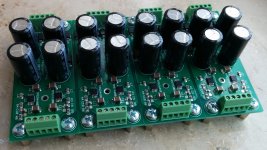
Due to moving my projects to switching power supplies I decided to sell four of my V1.0 assembled units (see attached pictures and post #6 for details). They were in use for several months in my multichannel preamp feeding the output buffers. They are configured for (+10)-0-(-10) VDC output with remote sensing on each rail. If you need other output voltages this can be arranged. Filter capacitors are 680uF/35V which allows reasonably high output voltage. The boards will tolerate up to 24+24VAC max input voltage and can output up to (+33)-0-(-33) VDC.
Price: 25 Euro/unit plus paypal fee and delivery.
Payment by paypal.
PM if interested.
Regards,
Oleg
Price: 25 Euro/unit plus paypal fee and delivery.
Payment by paypal.
PM if interested.
Regards,
Oleg
Attachments

I have a couple of assembled boards configured for (+15)-0-(-15) VDC output without remote sensing. I can easily change the output voltage and enable the remote sensing if requested. These boards were recently assembled on request but weren't claimed in the end. So I am offering them here. The boards are tested but otherwise unused. They will tolerate up to 24+24VAC max input voltage and can theoretically output up to (+33)-0-(-33) VDC. The assembled boards are exactly as shown in the opening post. I also offer 15VA Talema and 6VA Block PCB mounted transformers for a complete solution.
PM if interested.
Regards,
Oleg
PM if interested.
Regards,
Oleg
- Home
- Vendor's Bazaar
- TPS7A4901/TPS7A3001 low noise bipolar PSU PCBs