
It is meant solely as 78xx TO220 replacement? Make sure to have the thermal pad designed right with stitches to the other side of the PCB (fully copper that is acting as heatsink). An M3 hole for an additional heatsink might be a good idea. Maybe you think to need only 50 mA now but you might need 500 mA for a new project.
The ground arrangement around the 6 x 22 µF caps looks odd. Seems to serve no real purpose.
*Replacing 78xx regulators is the easy way out. Circuits are often very minimalistic with a single filter cap. In many cases a mini PCB with Schottky rectifiers, CLC and a TPS reg is recommended. More versatile as well.
Last edited:
thanks i got your point, i will make that changes. rest pcb is ok ? now i only have remove 4 22uf caps and leave 2 and send for the built ?It is meant solely as 78xx TO220 replacement? Make sure to have the thermal pad designed right with stitches to the other side of the PCB (fully copper that is acting as heatsink). An M3 hole for an additional heatsink might be a good idea. Maybe you think to need only 50 mA now but you might need 500 mA for a new project.
The ground arrangement around the 6 x 22 µF caps looks odd. Seems to serve no real purpose.
*Replacing 78xx regulators is the easy way out. Circuits are often very minimalistic with a single filter cap. In many cases a mini PCB with Schottky rectifiers, CLC and a TPS reg is recommended. More versatile as well.
No, datasheet tells 47 µF is recommended at the output. 2 x 22 µF at the output and a 10 µF at the input would be better. Make them all X7R or tantalum types with higher than necessary voltage ratings. I would add a 10 µF - ferrite bead - 10 µF at the input if space permits.
Thanks alot for helping. i re-made the pcb. please check will it work? i add a trimmer potentiometer for voltage regulation plus full one pcb as i need for project.No, datasheet tells 47 µF is recommended at the output. 2 x 22 µF at the output and a 10 µF at the input would be better. Make them all X7R or tantalum types with higher than necessary voltage ratings. I would add a 10 µF - ferrite bead - 10 µF at the input if space permits.
Attachments
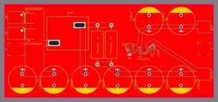
Ah you abandoned TO220 style?! At first glance it looks OK and it will work but: no mounting holes M3, way too large output caps (purpose?), no protection diode against discharging of that caps after power off, no screw or crimp connectors. Soldering wires direct to PCBs is old fashioned and with today's PCB material a design failure. You could do with half the amount of 4700 µF caps and still have very low ripple voltage as the regulator is 1A max. Positive is that you won't have HF/RF issues. A bridge rectifier or at least adding pads for 2 extra diodes is a choice.
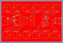
Please try to avoid sharp cornered PCB tracks and use 45 and 90 degrees angles. Tip: never label a pin of a PSU "in/out". "raw" or "unreg" suits better.
Please try to avoid sharp cornered PCB tracks and use 45 and 90 degrees angles. Tip: never label a pin of a PSU "in/out". "raw" or "unreg" suits better.
Last edited:
I agree with what JP wrote and would like to expand that adding a lot of capacitance after the regulator (between the reg and the load) defies the entire purpose of the regulator. I think it was discussed in Jan Didden's superreg thread at some moment. The immense capacitance as you have it effectively isolates the reg from the load, so it regulates the voltage at the first output capacitor terminals and not at the load. Just put the recommended value there which is needed for the regulator stability. I think you also can get away even with 4700 µF total capacitance before the reg. You are not constructing a power amplified PSU here. Split it into two 2200uF for the CL(R)C arrangement. You can also skip the R in your CL(R)C filter if you find a coil with enough DCR and >1A current rating. Don't forget the thermal pad connection of the regulator IC. You need a lot of heat sinking if you plan to push the reg to its maximum.
Oleg
Oleg
Thanks jean for assisting. no mounting holes are because I need 6 of these pcbs to feed DAC with independent supplies . so I was thinking get all 6 regulated supply on one big pcb so will make mounting holes on that PCB. i add connectors and follow as you guide me. am not sure about trimmer potentiometer and R5 in correct configuration ?. do i need to make any further changings in pcb ? THANKSAh you abandoned TO220 style?! At first glance it looks OK and it will work but: no mounting holes M3, way too large output caps (purpose?), no protection diode against discharging of that caps after power off, no screw or crimp connectors. Soldering wires direct to PCBs is old fashioned and with today's PCB material a design failure. You could do with half the amount of 4700 µF caps and still have very low ripple voltage as the regulator is 1A max. Positive is that you won't have HF/RF issues. A bridge rectifier or at least adding pads for 2 extra diodes is a choice.
Please try to avoid sharp cornered PCB tracks and use 45 and 90 degrees angles. Tip: never label a pin of a PSU "in/out". "raw" or "unreg" suits better.
Attachments
- Home
- Amplifiers
- Power Supplies
- TPS7A4701 need help ....!