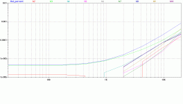
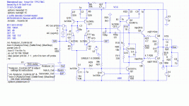
Some simulation results investigating TPC/TMC/‘pure Cherry’ and other obfuscating stuff. This started out as an exercise to see if LTspice can simulate ‘real life’ stuff from when commercial PA design was important to me.
I hope yus gurus will use it as a base point for some of the ‘compensation’ discussions in the threads on Bob & Doug’s books.
I’m also hoping Bob & Doug will be encouraged to do more ‘real life’ work on ‘pure Cherry’ rather than declare it unworkable.
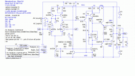
Starting point is Douglas Self’s fig 6.16 from his 4th ed. cos that’s close to what I was playing with in 1990. I’ve used Bob Cordell’s BJT models and some FET models from Scott Wurcer. These give the worst results of any models I can find so are likely to be close to real life. I’ve used mjl21194/3 cos they are the worst of Cordell’s OP devices and closest to Self’s mj802/4502 and the Sanyo device I used. This gave Self'’s results for THD with frequency … and also what I remember from 20+ yrs ago, which was encouraging.
Remember, all dis theory en simulation is useful … not cos the mathematical rigour or how it supports some pet theory .. but ONLY if it has some connection to ‘real life’ and gives us insights into the behaviour of amps and how to improve / design them.
Self & Cordell’s books are useful … not cos they expound many theories … but cos … for their pet topologies & ideas, they show ‘real life’ results from their experience and relate them to the simulations and calculations. eg asking Self to pontificate on the virtues of CFAs is non-productive. He doesn’t see the virtues … and more importantly, hasn’t done much ‘real life’ work on them.
I check virtual (and real) stability with a large variety of loads including pure capacitance from 33p to 100n as described in http://www.diyaudio.com/forums/analog-line-level/218373-discrete-opamp-open-design-231.html#post3266142
Some tweaking of stability done with added ‘zeros’ with judicious use of C2/7/9 and .TRANS. Check if C4 across the ‘bias spreader’ is appropriate and if something across R15 is needed.
BTW, this is all stuff you check & tweak in ‘real life’ … eg if you change devices in production
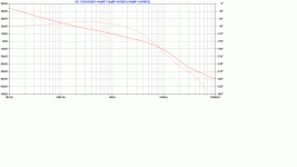
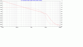
The Open Loop responses are done with a Tian probe (LTspice4\examples\Educational\LoopGain2.asc) at the –ve feedback point. Connect R5 to Ground for this. .AC closed loop responses (not shown) to check for excessive peaking. Connect V2 to R5 for this. For these and plain .TRANS, you need to get rid of the ..
First off is Two Pole Compensation (TPC) around the VAS. I’ve sorta used Cordell’s method by splitting Cdom and taking a tweak resistor R23 to earth. C7=4p7 from the stability tests.
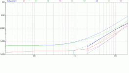
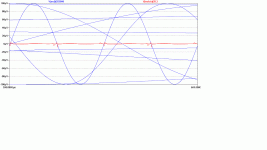
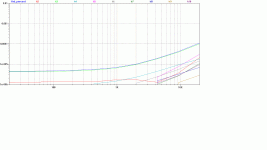
Distortion at 20V into 8R up to 10th harm. using Eugene Dvoskin’s Total Harmonic Analyzer from the LTspice Yahoo Group including stuff from jcx. The distortion residual shows 2 cycles of 20kHz with the fundamental superimposed at 0.01% to give some idea of scale. Ignore the lower freq waveforms. Takes a long time.
I hope yus gurus will use it as a base point for some of the ‘compensation’ discussions in the threads on Bob & Doug’s books.
I’m also hoping Bob & Doug will be encouraged to do more ‘real life’ work on ‘pure Cherry’ rather than declare it unworkable.
Starting point is Douglas Self’s fig 6.16 from his 4th ed. cos that’s close to what I was playing with in 1990. I’ve used Bob Cordell’s BJT models and some FET models from Scott Wurcer. These give the worst results of any models I can find so are likely to be close to real life. I’ve used mjl21194/3 cos they are the worst of Cordell’s OP devices and closest to Self’s mj802/4502 and the Sanyo device I used. This gave Self'’s results for THD with frequency … and also what I remember from 20+ yrs ago, which was encouraging.
Remember, all dis theory en simulation is useful … not cos the mathematical rigour or how it supports some pet theory .. but ONLY if it has some connection to ‘real life’ and gives us insights into the behaviour of amps and how to improve / design them.
Self & Cordell’s books are useful … not cos they expound many theories … but cos … for their pet topologies & ideas, they show ‘real life’ results from their experience and relate them to the simulations and calculations. eg asking Self to pontificate on the virtues of CFAs is non-productive. He doesn’t see the virtues … and more importantly, hasn’t done much ‘real life’ work on them.
I check virtual (and real) stability with a large variety of loads including pure capacitance from 33p to 100n as described in http://www.diyaudio.com/forums/analog-line-level/218373-discrete-opamp-open-design-231.html#post3266142
Some tweaking of stability done with added ‘zeros’ with judicious use of C2/7/9 and .TRANS. Check if C4 across the ‘bias spreader’ is appropriate and if something across R15 is needed.
BTW, this is all stuff you check & tweak in ‘real life’ … eg if you change devices in production
The Open Loop responses are done with a Tian probe (LTspice4\examples\Educational\LoopGain2.asc) at the –ve feedback point. Connect R5 to Ground for this. .AC closed loop responses (not shown) to check for excessive peaking. Connect V2 to R5 for this. For these and plain .TRANS, you need to get rid of the ..
- connection between InN and the base of Q3
- U1 the THD meter
First off is Two Pole Compensation (TPC) around the VAS. I’ve sorta used Cordell’s method by splitting Cdom and taking a tweak resistor R23 to earth. C7=4p7 from the stability tests.
Distortion at 20V into 8R up to 10th harm. using Eugene Dvoskin’s Total Harmonic Analyzer from the LTspice Yahoo Group including stuff from jcx. The distortion residual shows 2 cycles of 20kHz with the fundamental superimposed at 0.01% to give some idea of scale. Ignore the lower freq waveforms. Takes a long time.
Attachments
Last edited:
TMC
Next, we follow Michaelkiwanuka’s advice and take R23 to the output instead of ground to give Baxandall’s Transitional Miller Compensation (TMC).
I won’t enter the pedant’s debate about the equivalence or otherwise between TPC / TMC but note the final result shows very small improvement in distortion.
Neither of these compensation circuits have been optimised so I invite the various champions to offer improvements for both configurations on what I think is near a ‘real life’ device.
Attachments
pure Cherry
Prof. Edward Cherry suggested Cdom should be fed, not by the VAS collector, but from the output. I think someone calls it Output Inclusive Compensation but I like ‘pure Cherry’ as he not only popularised but also analysed it in various JAES papers.
Various gurus say it is difficult to make stable but in my experience, it is no worse than plain Miller.
Cherry offers the VAS emitter resistor R22 as a powerful tool to control the stability of this local loop. It reduces the transconductance of its input which. if made big enough, will always make things stable. I’ll offer a useful zero by decoupling R22 with C9 in the low nFs.
But pure Cherry is probably too frisky to use with Triple output stages and a supa dupa VAS. Maybe OK for Triples and a single BJT VAS but then its Ccb starts to matter.
This is the fabled 1ppm THD at 20kHz so this performance is well past the stage where layout, decoupling and grounding play an equal if not more important part in THD performance.
The circuit has some nice properties besides simplicity and high performance.
- The simple compensation means you can get very good +ve PSR by just adding C1 of equal value to the other side of the current mirror
- R7/8 were chosen to give equal Vce on Q10/11 & J1/2; for a noticeable effect on distortion. A bonus is that these larger resistors on the current mirror give very nice overload and recovery without extra clamps.
- Much less critical of Iq variations
- stability with ‘real life’ power rails.
- Huge bandwidth ... which can be limited by an input filter but I’m nervous. Simple extra stability dodges available which take it out of the realm of ‘pure Cherry’.
- –ve PSR rejection. C11 is at the base of Q1 not for PSR reasons but to ensure clean overload & recovery
- If built, the THD introduced by ‘real life’ layout, decoupling & grounding may swamp the improvement from J1/2 input cascode FETs. However, they may help CMR (and hence THD) if the amp is fed from eg a 10k pot. Remaining THD is mainly 3rd which sorta implies the input. (could be Beta droop in Outputs. Using MJL3281/1302 certainly reduces 3rd
- Better biasing schemes than the simple ‘bias spreader’ though its tolerance of Iq makes it less fussy than eg Self’s fig 6.16 Maybe a crude feedback control mechanism.
Attachments
Last edited:
Prejudices & obsessions
All the PA gurus have their own pet obsessions. This pseudo guru needs to declare his.
All the PA gurus have their own pet obsessions. This pseudo guru needs to declare his.
- Simplicity. I’m very old school in that I begrudge every single resistor .. let alone BJT in a design. I’ve been known to have young engineers on the carpet cos their ‘new’ design has more parts than what it replaces. Why have complexity or new fangled stuff if understanding old fogey stuff gives equal or better performance? After achieving a certain level of performance, I’m apt to throw bits out of the ‘final’ real world design to see what is not really needed. (eg J1/2, the FET input cascodes) For a DIY device, it probably makes more sense to count solder joints rather than bits.
- Unconditional Stability with load [deleted : 2 pages of pedalogical semantic rant] I’m really a speaker man and want amplifiers to handle the evil loads I dream up
- Overload performance. Like Bob Cordell, I believe this is the main reason why amplifiers sound different. Many (most?) Golden Pinnae amps show bursts of oscillation on part of a cycle on a real speaker load .. all dependent on the thermal, overload and signal history too.
- Layout, decoupling & grounding. Once you get below about 0.01%, these assume as great … or even greater … importance than more feedback or circuit complexity. Output devices soldered directly to PCB
- Manufacture & Test. I hate it when you need to warm up an item to do a final tweak. Mike Albinson & Peter Walker once told me this was the real reason they invented Current Dumping.
- Heretical obsession with current driving the output stage rather than the voltage drive favoured by most gurus. Distortion introduced is much lower order, amp isn’t slowed down at this critical point and higher loop gain around the evil outputs too.
Attachments
Last edited:
I like the simplest circuit with least bits with the best performance. 🙂What I miss in your good stuff are some conclusions.
What is the best you think? TPC or TMC
My goal is to get the same performance with even less bits & complexity. 😀
Hang on a second. Are you saying that amps preferred by "golden ears" types that you have *tested* ring, as in parasitic oscillation on reactive, "real world" speaker loads?? Or some other sort of oscillation??
This is a new sort of assertion on me. I find it surprising.
Perhaps some more information would help focus this??
_-_-
PS. overload or clipping performance does make a difference, assuming the amp gets clipped (a good assumption, in my view), which is why a whole lot of folks, myself included, do not prefer bipolar devices as the output devices of choice. Going farther down that road, I think it is part of the reason that so many seem to like zero loop feedback tube designs...
I think there are many distorted outputs that some Members prefer, but the listeners don't realise those corrupted amplifiers are not accurate.Hang on a second. Are you saying that amps preferred by "golden ears" types that you have *tested* ring, as in parasitic oscillation on reactive, "real world" speaker loads?? Or some other sort of oscillation??
This is a new sort of assertion on me. I find it surprising.
................
It does not surprise me at all.
Poor stability margins WILL give rise to a different sound from adequate stability margins.
I have said this in the past, more than once !
That's why I can't get excited about convoluted schemes to get astronomically high feedback. The simulated PPM level distortion goes down the plughole in the real world due to inductive coupling etc.[*] Layout, decoupling & grounding. Once you get below about 0.01%, these assume as great … or even greater … importance than more feedback or circuit complexity.
I remember Bob saying he's found many commercial amps that show oscillation on part of the waveform. I don't remember him saying anything specifically about golden ears approved amps.Hang on a second. Are you saying that amps preferred by "golden ears" types that you have *tested* ring, as in parasitic oscillation on reactive, "real world" speaker loads??
Yes. I hesitate to mention old, illustrious names that still post in these forums ... who immediately disown designs when proof of this is presented. 😱Are you saying that amps preferred by "golden ears" types that you have *tested* ring, as in parasitic oscillation on reactive, "real world" speaker loads?? Or some other sort of oscillation??
You don't need Audio Precision etc to see this. Any old scope, signal generator and a big old guitar speaker will do. Try frequencies just above the resonance and various levels.
But my serious investigations into Golden Pinnae stuff was circa 1990. Modern stuff may be better ... but somehow I don't think so. 😡
The educational efforts of Self, Cordell & a few other worthy gurus have done little to stem the Loony .. I mean Golden Pinnae brigade.
The classic LEAK, Radford and QUAD valve stuff don't misbehave like this. Their designers knew about this and are rightly contemptious of many Golden Pinnae designers.
Yes, let's not throw mud...
but I have yet to encounter this problem, happen across it when repairing and testing assorted and various amplifiers across many years.
otoh I have seen instability due to parasitic oscillations... but not that often.
that's why I am curious as to exactly what sort of instability you are seeing? what would I expect to see on the scope?
perhaps you'd care to grab a random amp and shoot a scope pic of this? seriously, I think it would be useful and educational.
_-_-bear
LSD / Grateful Dead
/OT
Hey Bear,
Has your nick anything to do with, or is it inspired by Owsley Stanley?
See: Owsley Stanley - Wikipedia, the free encyclopedia
Just wondering.
Cheers,
E.
/OT
Hey Bear,
Has your nick anything to do with, or is it inspired by Owsley Stanley?
See: Owsley Stanley - Wikipedia, the free encyclopedia
Just wondering.
Cheers,
E.
bear, I've been a beach bum for well over a decade so have little chance to measure Golden Pinnae stuff today... but I have yet to encounter this problem, happen across it when repairing and testing assorted and various amplifiers across many years.
otoh I have seen instability due to parasitic oscillations... but not that often.
that's why I am curious as to exactly what sort of instability you are seeing? what would I expect to see on the scope?
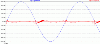
But the effect is usually not subtle. The guitar speaker was one of my standard tests of stability.
This pic is of something completely different but if you remove the crossover spikes from the red curve, you get an idea of what to expect. Usually only on part of a cycle. It may or may not go away as the amp heats up, cools down, signal level & history etc.
Many (most?) Golden Pinnae amps, especially those without an output inductor, exhibit this often very obvious 'feature'. No wonder they sound different. 😀
A more subtle example may not be seen on a cheap scope. You may find THD becomes very bad on very specific loads when it is excellent on 8R resistors. Curing the instability restores good THD on these loads.
I'm sure Bob Cordell has mentioned this, either in his book or on some thread here.
Attachments
Edmond,
Ha ha. No, but I certainly knew who he was, although I never met him. I did correspond with him about a decade ago... I was a pretty big fan of early Grateful Dead too. Someone else who is active here actually knew him back in the day... 😀
_-_-bear
Ha ha. No, but I certainly knew who he was, although I never met him. I did correspond with him about a decade ago... I was a pretty big fan of early Grateful Dead too. Someone else who is active here actually knew him back in the day... 😀
_-_-bear
kgrlee, very interesting graph. generated by a simulation or by actual measurement?? Can't say I have ever seen this first hand. Makes me want to try your "test protocol". So you are suggesting that this happens into inductive loads rather than capacitive??
And are you wrestling here with an artifact found with class AB switching only?
But of course all this is OT, no not output transformer, to the original question you raised.
_-_-bear
And are you wrestling here with an artifact found with class AB switching only?
But of course all this is OT, no not output transformer, to the original question you raised.
_-_-bear
I think with this type of artifact, you need to identify whether it is loop gain related oscillation, or whether it is parasitic. If loop gain related, the solution is to sort the compensation out. And I absolutely believe in output coils (with 2r2 or 3r3 damping resistors) and Zobel networks ( on the amplifier side of the coil!).
Parasitics are usually a bit more difficult to put your finger on. I have seen the problem in EF3, but the fixes are easy to implement and they work very well. Cascode instability is also another one, as is parameter modulation ( Cob specifically).
Parasitics are usually a bit more difficult to put your finger on. I have seen the problem in EF3, but the fixes are easy to implement and they work very well. Cascode instability is also another one, as is parameter modulation ( Cob specifically).
Excellent to see such work.
It would be nice to see the Bode plots done so that 180 phase is the same line as 0 dB.
Quicker to interpret, and a sensible standard to simplify comparisons.
Optimised TMC can do at least as well as OIC. At worst the optimisation may end up with a zero ohm resistor to the output and a zero farad capacitor to the OPS input, to produce OIC.
Best wishes
David
It would be nice to see the Bode plots done so that 180 phase is the same line as 0 dB.
Quicker to interpret, and a sensible standard to simplify comparisons.
Has anyone pointed out the obvious, that OIC (AKA Cherry) is just a subset of TMC?Neither of these compensation circuits have been optimised so I invite the various champions to offer improvements...
Optimised TMC can do at least as well as OIC. At worst the optimisation may end up with a zero ohm resistor to the output and a zero farad capacitor to the OPS input, to produce OIC.
Best wishes
David
Last edited:
And I absolutely believe in output coils (with 2r2 or 3r3 damping resistors) and Zobel networks ( on the amplifier side of the coil!).
Hi Andrew
Why do you prefer Zobel on the amp side?
Best wishes
David
As I said earlier, I've been a beach bum for a long time so can't really do sensible measurements this millenium.... generated by a simulation or by actual measurement?? Can't say I have ever seen this first hand. Makes me want to try your "test protocol". So you are suggesting that this happens into inductive loads rather than capacitive??
The pic is a simulation of something else entirely .. but you asked for something to look for on a scope.
I've seen it on both inductive & capacitive loads.
A capacitance box (like in school lab experiments) is a quick and easy way to check capacitive loads formally.
The guitar speaker is more cumbersome and I don't have a proper formal procedure. But unlike with capacitors, IME the amp is unlikely to go up in smoke so you can take your time. 😀
One of the culprits was a large famous Class A Golden Pinnae Amp (actually 2 of their models) in Stereophile/TAS good books... are you wrestling here with an artifact found with class AB switching only?
Your question is entirely relevant as I was hoping some gurus would pontificate on the 'real life' stabilty of the 3 versions I presented.
__________________
Bonsai, I obviously have my own ideas but what are your favourite easy fixes to try with 'parasitics'?bonsai said:Parasitics are usually a bit more difficult to put your finger on. I have seen the problem in EF3, but the fixes are easy to implement and they work very well
__________________
I'm a newbie with LTspice and am often frustrated by the auto scaling.Dave Zan said:It would be even better to see the Bode plots done so that 180 phase is the same line as 0 dB.
Main grouse at present is I must show phase from 0 to -360 so can't have it cycle and show +/-180. I tried to turn the Tian probe round but I failed to get that to work. Suggestions gratefully received. 😡
My obvious contention is that TMC has no advantage over 'pure Cherry' and is usually worse.Optimised TMC can do at least as well as OIC. At worst the optimisation may end up with a zero ohm resistor to the output and a zero farad capacitor to the OPS input, to produce OIC.
I'm hoping someone will show differently using my examples. I've made all my models available and the circuit is simple enough not to obfuscate the issue. I believe they are 'realistic' 😱 in as much as a sim can be realistic 😕
I've my own opinions re: TPC vs TMC but in practice, there is little difference.
[deleted: 21 pages of pedantic rant about why it should be called 'pure Cherry'] 😀
Last edited:
- Home
- Amplifiers
- Solid State
- TPC vs TMC vs 'pure Cherry'

