Hi,
If you examine the EVM manual, then there are some extra components on the inputs, namely 100ohm resistors and 100pF capacitors to ground.
You should not be getting oscillations, and i doubt the extra components on the inputs make a difference, then again, could be an issue, but i think if you followed the component count and layout as per the EVM for the TPA3255 IC you should have a working system.
The TI forum is very helpful too. The engineers will be able to state what the issue is from the symptoms if you copy the schematic and PCB for examination.
Regards,
Shadders.
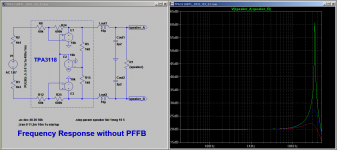
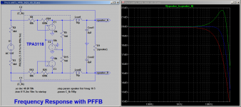
100p/100R respresents a LP with a corner frequency close to 16MHz - not so effective at 50kHz. Same applies to the proposed snubbers - not effective in dampening, if you do the math. The post-filter-feedback proposed by TI will tame a good deal of that resonant peaking - but not as perfect as my solution, and it requires a very good op-amp with very low THD at high output level and a complex postfilter feedback network to achieve the goal. If you want to improve THD and noise for about 7dB then this is the way to go. I am not so eager in maxing these parameters at any expense - because they are pretty good imho even without further improvement.Hi,
If you examine the EVM manual, then there are some extra components on the inputs, namely 100ohm resistors and 100pF capacitors to ground.
You should not be getting oscillations, and i doubt the extra components on the inputs make a difference, then again, could be an issue, but i think if you followed the component count and layout as per the EVM for the TPA3255 IC you should have a working system.
The TI forum is very helpful too. The engineers will be able to state what the issue is from the symptoms if you copy the schematic and PCB for examination.
Regards,
Shadders.
On the other hand you may consider the relevance of my findings - and that is just a different story.
Assume that 99.9% of incoming audio signal is D/A converted mp3 or similar with a sample rate of 44.1 or 48 kHz - then there will never be any significant input signal in the 50kHz-region that can excite the output resonant tank. Relying on that prerequisite my findings may look academical indeed,
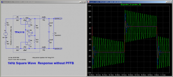
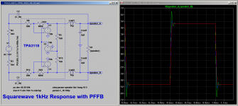
But I am an old school guy and for me any amp must be capable to deliver some proper square output, without resonant peaking.
The eye (on the scope) listens as well! 🙂
Last edited:
Wow, I didn't know you were the author of this paper, thank you for your contribution. Would you mind sharing the link the that thread? I've been unsuccessful in finding it through google, only the paper appears in the results.Nice that you discovered us. I recommend variant 2, just because I am the author of these contributions and the differenciating feedback was my idea. And meanwhile there is nothing I have to add from my side. Snubbers will burn when you drive the amp with sufficciant 50kHz input. And if you don't - you do not need them😉
Hi,100p/100R respresents a LP with a corner frequency close to 16MHz - not so effective at 50kHz. Same applies to the proposed snubbers - not effective in dampening, if you do the math. The post-filter-feedback proposed by TI will tame a good deal of that resonant peaking - but not as perfect as my solution, and it requires a very good op-amp with very low THD at high output level and a complex postfilter feedback network to achieve the goal. If you want to improve THD and noise for about 7dB then this is the way to go. I am not so eager in maxing these parameters at any expense - because they are pretty good imho even without further improvement.
On the other hand you may consider the relevance of my findings - and that is just a different story.
Assume that 99.9% of incoming audio signal is D/A converted mp3 or similar with a sample rate of 44.1 or 48 kHz - then there will never be any significant input signal in the 50kHz-region that can excite the output resonant tank. Relying on that prerequisite my findings may look academical indeed,
But I am an old school guy and for me any amp must be capable to deliver some proper square output, without resonant peaking.
The eye (on the scope) listens as well! 🙂
The design does not implement PFFB, and is the minimal implementation of the TPA3255. The internal feedback as indicated in the TPA3255 manual show that the feedback path has a connection to the input pins. I agree that the input components will probably have no effect, as when the amplifier is excited by an input signal the oscillations are still present.
The output components and connections are as per the datasheet. There must be an effect which is causing positive feedback for the oscillations to occur. If the output components were removed temporarily then this may assist in determining where the issue is located. Do the oscillations stop or change in frequency ?
My approach is that adding components to a system may stop the oscillation, but it does not indicate the underlying cause. The TPA3255 in its current basic design should be stable, but this seems to be a problem for the design being discussed. It could be something as simple as wrong component values used for the oscillator input. So removing components to determine changes may help greatly in locating the issue.
Regards,
Shadders.
This is valuable input, I will be adding those components to see if they help, otherwise they are good to have on a complete design.Hi,
The design does not implement PFFB, and is the minimal implementation of the TPA3255. The internal feedback as indicated in the TPA3255 manual show that the feedback path has a connection to the input pins. I agree that the input components will probably have no effect, as when the amplifier is excited by an input signal the oscillations are still present.
The output components and connections are as per the datasheet. There must be an effect which is causing positive feedback for the oscillations to occur. If the output components were removed temporarily then this may assist in determining where the issue is located. Do the oscillations stop or change in frequency ?
My approach is that adding components to a system may stop the oscillation, but it does not indicate the underlying cause. The TPA3255 in its current basic design should be stable, but this seems to be a problem for the design being discussed. It could be something as simple as wrong component values used for the oscillator input. So removing components to determine changes may help greatly in locating the issue.
Regards,
Shadders.
Hi,This is valuable input, I will be adding those components to see if they help, otherwise they are good to have on a complete design.
If you remove the output inductor that will remove all components from the amplifier output apart from the 33nF. From here you can then determine if the output components are causing or significantly affecting the oscillation.
Regards,
Shadders.
I think this is stromrichter member area, so you have to sign in.Wow, I didn't know you were the author of this paper, thank you for your contribution. Would you mind sharing the link the that thread? I've been unsuccessful in finding it through google, only the paper appears in the results.
Wow, I didn't know you were the author of this paper, thank you for your contribution. Would you mind sharing the link the that thread? I've been unsuccessful in finding it through google, only the paper appears in the results.
I have done but still can’t find it after a lot of searching!I think this is stromrichter member area, so you have to sign in.
I used PCBWAY's PCB and assembly service. They sourced all the parts.Hi,
Can you confirm where you purchased the output inductors from ?
Regards,
Shadders.
https://stromrichter.org/showthread.php?tid=4100&highlight=postfilter+feedbackI have done but still can’t find it after a lot of searching!
Reading these old threads nowadays I found them quite entertaining. Provided you understand the German language.
In the meantime I checked my repos and found some LTSpice simulations depicting the effect of differentialting postfilter feedback. Originally intended for TPA3118 these are generic and apply to TPA3255 as well as to many other class-D chips.
Attachments
-
FQR_TPA3118BTL_2021_03_21.asc3.5 KB · Views: 116
-
FQR_TPA3118BTL_PFFB_2021_03_21.asc4 KB · Views: 113
-
 Simu_FQR_TPA3118.png24 KB · Views: 186
 -
 Simu_FQR_TPA3118_PFFB.png27.2 KB · Views: 189
 -
 Simu_SQR_1kHz_TPA3118.png26.3 KB · Views: 178
 -
 Simu_SQR_1kHz_TPA3118PFFB.png25.6 KB · Views: 180
 -
SQR_1kHz_TPA3118BTL_2021_03_21.asc3.5 KB · Views: 108
-
TPA3118BTL_PFFB_2021_03_22.asc4 KB · Views: 101
Hi,I used PCBWAY's PCB and assembly service. They sourced all the parts.
Is it possible that they have used a 1uH inductor, and a 10uF capacitor ? That will have the same resonant frequency as you are seeing, but the capacitive load may cause the instability you are experiencing.
Regards,
Shadders.
Okay so I've managed to solve the issue, the oscillation is gone to the point I can't see it above the noise and the switching residue on the scope.
The fix was simple, a 470uH inductor on the power input of each amplifier module. I think the oscillation was coming from noise on the power supply lines induced by the amplifiers themselves as oscillation in adjacent amplifiers would reduce (not disappear) if an inductor was fitted to a single module. I fit inductors to each one and now all good.
I tried fitting the inductor as a last ditch effort to solve the problem. I tried the differentiating capacitor however this did nothing for the major oscillation I saw.
Hi,
What power supply are you using ?
I checked the schematic you provided and 4,700uF capacitance for the main power supply should be sufficient. so having to add a 470uH inductor on the power line indicates issues with the design. In saying that, maybe others have more experience and this is a standard solution to the TPA implementation, or class D in general.
Regards,
Shadders.
Yes quite possibly there could be something more fundamental wrong with the design. However, I don’t plan on making any more of these modules, taking the design any further or sharing it with anyone. Also, I thoroughly tested the stability into multiple loads including a square wave test into 4R parallel with 100nF with minimal ringing. For this reason I’m content using the design.Hi,
What power supply are you using ?
I checked the schematic you provided and 4,700uF capacitance for the main power supply should be sufficient. so having to add a 470uH inductor on the power line indicates issues with the design. In saying that, maybe others have more experience and this is a standard solution to the TPA implementation, or class D in general.
Regards,
Shadders.
If I do anymore designs with the TPA3255 in the future I will go for a very different layout and thoroughly reconsider my approach.
- Home
- Amplifiers
- Class D
- TPA3255 oscillation issues