But a regulated supply won't compensate for low mains voltage or power demands that cause the the rail voltage to sag.
Rather than increase complexity with a regulator, seems to make more sense to spend the money on a more adequate PS.
I mean a complete new regulated switching mode power supply. When designed properly it will hardly sag and be independent from the mains voltage. The new TPA3255 will need at least 500W, it make sense to use switching mode power.
Rob
I finally read through this entire thread after finding it yesterday, lots going on here. I have a question about using the 3251 chip in a self powered speaker. Since I will have one of these chip amps in each enclosure for the bass/mid and don't need two channels what would be the best option for using this chip? I am wondering if it would be possible to use this as a PBTL into either a 8 or 4 ohm load, I get to chose the impedance since I am specifying the voicecoil. Is this practical or do I just use 1/2 the chip and run the BTL configuration and perhaps leave the other channel for an expansion channel for a potential subwoofer output for later? I was originally looking at the IRS2092 but the 3251 or even the 3255 looks like a simpler and perhaps better solution. I'm looking for a peak output at 1% or less distortion of a max of 120 watts @8ohms that should give me a 3db headroom so no clipping allowed. As most have said most of the time a few watts will be enough but the speakers are capable of some real spl level so I am just covering my behind with enough power so the speakers never see a clipping amp and and the distortion level never goes above 1% from the amplifier.
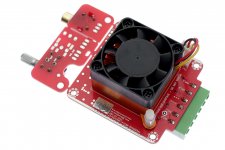
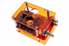
I have a heatsink that is approximately 14"H x 4" wide x 1" fin height with a 1/4" base thickness to mount this amp onto, there will also be a low powered chip amp, only 10 watts necessary for the tweeter that will use the same heatsink. The fins are in a vertical orientation and are 14" height.
I had many question while reading the thread but the comments were so old I didn't want to make anyone repeat what had already been said.
Thanks to Dr Mod, 5th element and Gmad for all the great design work you all did throughout the thread.
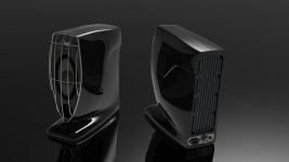
ps. Ignore the wireform grill that has gotten the axe and something more elegant will be shown soon.
I have a heatsink that is approximately 14"H x 4" wide x 1" fin height with a 1/4" base thickness to mount this amp onto, there will also be a low powered chip amp, only 10 watts necessary for the tweeter that will use the same heatsink. The fins are in a vertical orientation and are 14" height.
I had many question while reading the thread but the comments were so old I didn't want to make anyone repeat what had already been said.
Thanks to Dr Mod, 5th element and Gmad for all the great design work you all did throughout the thread.
ps. Ignore the wireform grill that has gotten the axe and something more elegant will be shown soon.
Attachments
Last edited:
What would be the cost of a bare PCB, and, if you have it, component BOM cost?
BOM is at ~$100-110.
This is for audio, where we only need high power to avoid clipping on peaks, so who cares about continuous power?
I sure don't; with a very conservative crest factor of 6 dB, average power is only 1/4 of peak.
Which is what I said. But TI have always rated and measure their amplifiers at continuous sine driven power. No doubt the chip is capable of that but only if you include some thermal solution that no end manufacturer is ever going to use.
I am just surprised that they chose to use the same tiny SMD package where a larger one would have made far more sense. Also a few people do use these devices for 'off label' applications that are not audio related where power delivery could also be very important.
Sounds like the power supply design is a companion along with this amp design.I mean a complete new regulated switching mode power supply. When designed properly it will hardly sag and be independent from the mains voltage. The new TPA3255 will need at least 500W, it make sense to use switching mode power.
Looking at available AC/DC converters with 36VDC and 10 or more amps are not cheap nor easy to find.
What are people who are evaluating these new chips, using for power supplies to test their designs out with?
There's alot of Meanwell power supplys available.
I.e.:
NES-350-36 Mean Well | Mouser
http://www.mouser.com/ds/2/260/NES-350-SPEC-806427.pdf
I actually use an unregulated LLC power supply which is fine and doing great.
I.e.:
NES-350-36 Mean Well | Mouser
http://www.mouser.com/ds/2/260/NES-350-SPEC-806427.pdf
I actually use an unregulated LLC power supply which is fine and doing great.
BOM is at ~$100-110.
Not too bad. Where can I purchase the boards? Would love to play with a mord board. Am I correct in assuming that this board will work with the 3255 once it is available? With some component tweaks obviously.
Due to limited project time at the moment, i could only offer bare boards + bom + assembly book. You'd need a stencil from i.e. Oshstencils as well for comfortable soldering.
Just drop me a pm.
Just drop me a pm.
Thx that Meanwell looks to be economical for this app.
I missed that one in my search, I had my selection filter set for >=10A.
What do you mean by LLC?, Inductor Inductor Capacitor?
a traditional ac line step down transformer, rectifier, filter of what VA rating?
I missed that one in my search, I had my selection filter set for >=10A.
What do you mean by LLC?, Inductor Inductor Capacitor?
a traditional ac line step down transformer, rectifier, filter of what VA rating?
Due to limited project time at the moment, i could only offer bare boards + bom + assembly book. You'd need a stencil from i.e. Oshstencils as well for comfortable soldering.
Just drop me a pm.
All I would really need is a bare board and a schematic ;-) . I hand populate double sided smd stuff, without a solder mask, regularly down to 0402 and 0.4mm QFN for work. All with no magnification!
Will drop you a PM this afternoon.
What do you mean by LLC?, Inductor Inductor Capacitor?
a traditional ac line step down transformer, rectifier, filter of what VA rating?
You'll have to ask "voltwide" for any details.
PSU is shown here:
http://www.diyaudio.com/forums/class-d/276982-tpa3251d2-60.html#post4600084
and here:
http://www.diyaudio.com/forums/class-d/276982-tpa3251d2-60.html#post4600163
As far is i remember it's in the 250W cont. 350-400W peak section.
I hand populate double sided smd stuff, without a solder mask, regularly down to 0402 and 0.4mm QFN for work. All with no magnification!
Time will come.. 😀
Last edited:
very nice work Drmod 🙂 bravo.
may I mention Connexelectronic smps power supplies. They are designed with audio in mind, with larger output caps and low emi. Some have output LC filter. Smaller form factor than the Meanwel industrial bricks PS. They are quite reliable, various power and voltage and reasonably priced.
Connexelectronic
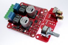
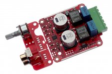
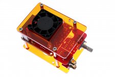
Tthat's incredible how small this tiny amp is on the photographs !
WHat is the value of the "big" blue MKPs ?
Does a 250V PPS smd cap could be suitable and precise enough here ? Or do you need just the lowest Tang loss possible with the cap you use here?
WHat is the value of the "big" blue MKPs ?
Does a 250V PPS smd cap could be suitable and precise enough here ? Or do you need just the lowest Tang loss possible with the cap you use here?
Thanks. The caps are 1uF 450V MKP choosen for low tang - right. I've had MKTs on the bigger blue pcb, worked as well without getting warm/hot. (1uF 63V WIMA)
But there's more heat/loss in MKT compared to MKP. Still waiting for the chinese CBB drops to test.
From the simulations, a 250V X7R would also do, but package size isn't that "crack-proof". (2520)
Have a look here:
http://www.diyaudio.com/forums/class-d/276982-tpa3251d2-56.html#post4573529
SMD PPS are very delicate and heat sensitive, i wouldn't recommend.
Sounds like the power supply design is a companion along with this amp design.
Looking at available AC/DC converters with 36VDC and 10 or more amps are not cheap nor easy to find.
What are people who are evaluating these new chips, using for power supplies to test their designs out with?
Hi,
TI recommends to use a stabilized lab power supply for their evaluation board. For a commercial product, it seems a stabilized SMPS is needed to get the most out of this chip. Of course a normal transformer can be used, but at 300+ VA (for 4 ohm use and to minimize sag) this is going to be a monster.
Most ready-to-use SMPS are for industrial use, have a loud fan and many have high HF ripple (100mV or so), not so good for home audio.
I will take the challenge and design my own SMPS for this chip. I never designed an SMPS before so this will be fun.
Please share you endeavor as it unfolds!
//
Using a multiphase approach would help you on this.
But I wouldn't call 100mV HF ripple a real problem. ( That's 0.3% full scale 36V ) Your supply needs some ripple to feed the regulation loop.
But I wouldn't call 100mV HF ripple a real problem. ( That's 0.3% full scale 36V ) Your supply needs some ripple to feed the regulation loop.
- Home
- Amplifiers
- Class D
- TPA3251d2