TI has released TPA3251d2 'AKITA" higher power analog in class D chip with higher order modulator similar to Hypex NCore but with pre filter feedback. First heard about it at CES 3+ years ago. Can be configured as 1,2,3 or 4 channel with 36 volt supply for output stage.
I'm really curious how this chip sounds. Pretty impressive description:
"TPA3251D2 is a high performance class-D power amplifier that enables true premium sound quality with class-D efficiency. It features an advanced integrated feedback design and proprietary high-speed gate driver error correction (PurePath™ Ultra-HD). This technology allows ultra low distortion across the audio band and superior audio quality."
I hope the chinese manufacturers will take the first steps soon.
TPA3251D2 THD Curves
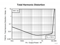
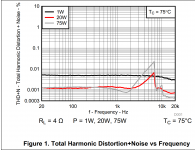
This is a closed loop part with pre-filter feedback. THD vs power (at 1KHz) & THD vs Frequency curves from June 2015 datasheet attached. I'd like to try a differential input, BTL output implementation.
TI website has samples: TPA3251D2 | Mid/High-Power Class D Amplifiers | Audio | Sample & buy
This is a closed loop part with pre-filter feedback. THD vs power (at 1KHz) & THD vs Frequency curves from June 2015 datasheet attached. I'd like to try a differential input, BTL output implementation.
TI website has samples: TPA3251D2 | Mid/High-Power Class D Amplifiers | Audio | Sample & buy
Attachments
Some short calculation for the required heatsink, worst case:
Rds_on (high/low side): 0.1R
Imax: 14A
Tambient: 30°C
Rth_jc(Top): 0.36°C/W
Power dissipation per channel:
Pd_channel = I²R = Imax²*2*Rds_on = 14A²*2*0.1R = 196A*0.2R = 39.2W
Power dissipation total:
Pd_total = 2*Pd_channel = 2*39.2W = 78.4W
Tcase = Tjunction - Rth_jc * Pd_Total = 125°C - 0.36°C/W * 78.4W = 125°C - 28.224°C = 96.776°C
Rth_heatsink = (Tcase - Tambient) / Pd_total = (96.776°C - 30°C) / 78.4W = 0.85°C/W
Rth_heatsink includes thermal conductivity of heatsink grease.
--------------
Lets do the calculation again for Irms (sinus power):
Rds_on (high/low side): 0.1R
Imax: 14A
Tambient: 30°C
Rth_jc(Top): 0.36°C/W
Power dissipation per channel:
Irms = Imax*sqrt(2) = 14A*0.707 = 9.9A
Pd_channel = Irms²R = Irms²*2*Rds_on = 9.9A²*2*0.1R = 98A*0.2R = 19.6W
Power dissipation total:
Pd_total = 2*Pd_channel = 2*19.6W = 39.2W
Tcase = Tjunction - Rth_jc * Pd_Total = 125°C - 0.36°C/W * 39.2W = 125°C - 14.112°C = 110.888°C
Rth_heatsink = (Tcase - Tambient) / Pd_total = (110.888°C - 30°C) / 39.2W = 2.1°C/W
Rth_heatsink includes thermal conductivity of heatsink grease.
Much better. 😀
As music is normally not pure fixed frequency sine wave the maximum temperature will likely not reached even at full power.
----------------------------------------------------------------------
Lastly, for normal use, with an estimated programm factor of 0.5 there will be:
Rds_on (high/low side): 0.1R
Imax: 14A
Music programm factor (mpf): 0.5
Allowed max junction temperatur: 90% from Tj = 0.9*125°C = 113°C
Tambient: 35°C
Rth_jc(Top): 0.36°C/W
Power dissipation per channel:
Irms = Imax*sqrt(2) = 14A*0.707 = 9.9A
Iprog = Irms * mpf = 4.45A
Pd_channel = Iprog²R = Iprog²*2*Rds_on = 4.45A²*2*0.1R = 19.8A*0.2R = 3.96W
Power dissipation total:
Pd_total = 2*Pd_channel = 2*3.96W = 7.92W
Tcase = Tjunction - Rth_jc * Pd_Total = 113°C - 0.36°C/W * 7.92W = 113°C - 2.85°C = 110.15°C
Rth_heatsink = (Tcase - Tambient) / Pd_total = (110.15°C - 35°C) / 7.92W = 9.5°C/W
Rds_on (high/low side): 0.1R
Imax: 14A
Tambient: 30°C
Rth_jc(Top): 0.36°C/W
Power dissipation per channel:
Pd_channel = I²R = Imax²*2*Rds_on = 14A²*2*0.1R = 196A*0.2R = 39.2W
Power dissipation total:
Pd_total = 2*Pd_channel = 2*39.2W = 78.4W
Tcase = Tjunction - Rth_jc * Pd_Total = 125°C - 0.36°C/W * 78.4W = 125°C - 28.224°C = 96.776°C
Rth_heatsink = (Tcase - Tambient) / Pd_total = (96.776°C - 30°C) / 78.4W = 0.85°C/W
Rth_heatsink includes thermal conductivity of heatsink grease.
--------------
Lets do the calculation again for Irms (sinus power):
Rds_on (high/low side): 0.1R
Imax: 14A
Tambient: 30°C
Rth_jc(Top): 0.36°C/W
Power dissipation per channel:
Irms = Imax*sqrt(2) = 14A*0.707 = 9.9A
Pd_channel = Irms²R = Irms²*2*Rds_on = 9.9A²*2*0.1R = 98A*0.2R = 19.6W
Power dissipation total:
Pd_total = 2*Pd_channel = 2*19.6W = 39.2W
Tcase = Tjunction - Rth_jc * Pd_Total = 125°C - 0.36°C/W * 39.2W = 125°C - 14.112°C = 110.888°C
Rth_heatsink = (Tcase - Tambient) / Pd_total = (110.888°C - 30°C) / 39.2W = 2.1°C/W
Rth_heatsink includes thermal conductivity of heatsink grease.
Much better. 😀
As music is normally not pure fixed frequency sine wave the maximum temperature will likely not reached even at full power.
----------------------------------------------------------------------
Lastly, for normal use, with an estimated programm factor of 0.5 there will be:
Rds_on (high/low side): 0.1R
Imax: 14A
Music programm factor (mpf): 0.5
Allowed max junction temperatur: 90% from Tj = 0.9*125°C = 113°C
Tambient: 35°C
Rth_jc(Top): 0.36°C/W
Power dissipation per channel:
Irms = Imax*sqrt(2) = 14A*0.707 = 9.9A
Iprog = Irms * mpf = 4.45A
Pd_channel = Iprog²R = Iprog²*2*Rds_on = 4.45A²*2*0.1R = 19.8A*0.2R = 3.96W
Power dissipation total:
Pd_total = 2*Pd_channel = 2*3.96W = 7.92W
Tcase = Tjunction - Rth_jc * Pd_Total = 113°C - 0.36°C/W * 7.92W = 113°C - 2.85°C = 110.15°C
Rth_heatsink = (Tcase - Tambient) / Pd_total = (110.15°C - 35°C) / 7.92W = 9.5°C/W
Yeah, let's make a small board <=10x5cm. 🙂
Please do that!!!
Most of the commonly used chips are 5+ years old.
Did you see the TAS57xx series with integrated DSP stuff?
If i were an engineer...
this is one ds:
http://www.ti.com/lit/ds/symlink/tas5756m.pdf
this is the user manual for the software:
http://www.ti.com/lit/ug/slau577a/slau577a.pdf
http://www.ti.com/lit/ds/symlink/tas5756m.pdf
this is the user manual for the software:
http://www.ti.com/lit/ug/slau577a/slau577a.pdf
PCB layout description in the data sheet seems quite detailed - who's got a spare weekend to put something together? 😀
/U.
/U.
That's a pretty awesome looking chip.
Yes, I'll make an amplifier card for it 🙂
you are the man!!!!
That's a pretty awesome looking chip.
Yes, I'll make an amplifier card for it 🙂
Please let me know what heatsink solution you choose, I'm still unsure. BGA heatsinks are quite expensive.
That's a pretty awesome looking chip.
Yes, I'll make an amplifier card for it 🙂
Excellent news!
That's a pretty awesome looking chip.
Yes, I'll make an amplifier card for it 🙂
Awesome!! May be a completely built amp card😉. This is something that I could really use. The 3116's output is a bit low for my 83 db speaker.
Regards,
Haven't made my mind up yet.Please let me know what heatsink solution you choose, I'm still unsure. BGA heatsinks are quite expensive.
Heatsinks are a mechanical pain in the ***. I might do something like mount the card to an aluminum plate with the TPA on the bottom side - I'd have to "swiss cheese" the plate a bit to allow clearance for component leads, I'll play around with the idea over the next few days.
Okay. I think i'll go for a "Fischer Elektronik" SK612 37.5 with off-centered mounting drills (Heatsink performance is about 3.4K/W then) and split decoupling (1u 1206/1210 + 100n 0612 reversed).
With the infos from here:
http://www.xilinx.com/support/documentation/application_notes/xapp623.pdf
The placement of the 1u isn't that critical.
With the infos from here:
http://www.xilinx.com/support/documentation/application_notes/xapp623.pdf
The placement of the 1u isn't that critical.
- Home
- Amplifiers
- Class D
- TPA3251d2