Warning, the following is just my very subjective experience, no measurements (except volume).
Yesterday I compared my FX502PRO amp against my self built amp with TPA3255EVM.
The TPA3255 amp uses a linear power supply with quality toroid and filter capacitors, DC filter on the mains side, noise filter on the line input and so on. The FX502S is standard and uses the 24V/4A power supply that comes with the amp. Not entirely fair.
I used the same equipment in the whole test, just switching cables between listing sessions. The FX502S have a higher gain so I had to adjust the volume control between sessions.
My speaker are a pair of XTZ99.26, floor standing speakers with89dB/W efficiency and an impedance between 4 and 8 ohms. Listening volume was about 70-80 dB at one meter from the speaker, it should not have been very taxing for the smaller amp.
The sound
They are sound-wise clearly both from the same family. But the sound from the FX502S is a bit muddy, it lacks precision in the bass, even if there was a fair amount of rumbling bass to it, just not the same amount of low level bass I am
used to from the EVM board. Resolution in the whole spectrum is lacking, the
sound comes mostly from a point in between the speakers, not so much a sound stage.
I would say that it is an OK amplifier and definitely worth the money, but that's about it.
Then I swapped the op-amps from the NE5532 to the much better LME49720NA and things started to lighten up! Now there are much better resolution in the whole spectrum and there is the impression of a wider sound stage. The bass is not so dominant, it is the midrange (voices) and the treble that benefits most from the new op-amps. It might be even better from another several hours burn in. Time will tell. Later I will also check for any high frequency oscillation on the output of the LME op-amp's.
Still it is no match for the TPA3255EVM which shows that there is much more to an amplifier than the op-amp's and the TPA IC. Sound wise the EVM amplifier is much more balanced, more dynamic and have better resolution over the whole audible spectrum with a much deeper and better defined bass, better sound-stage and a calm and authority that speaks of class. I still is not nearly as good as the best class AB amplifier I have had, but that was a magnitude more expensive amplifier.
Now, if I could only swap the op-amp's to a LME49720....
Hi, thanks for your impressions. I have the FX502S with LME49270 AND a linear PS. I have to say I agree 100% with your impressions, they match mine. It is interesting that 3255 has that much better sound. I may consider picking up the 3255 board from 3e-audio-- I will be getting new speakers soon but they are a bit less sensitive than current, so maybe I will need some more power. Unfortunately I cant see any fully built amps based on 3255 🙁 There is a 3255 evm clone from the china stores at about $57 I will be picking one up hopefully it is a match for the EVM which costs more and is harder to get. Like you I wish the opamps were socketed... is it hard to solder SOIC?
Last edited:
Hi, thanks for your impressions. I have the FX502S with LME49270 AND a linear PS. I have to say I agree 100% with your impressions, they match mine. It is interesting that 3255 has that much better sound. I may consider picking up the 3255 board from 3e-audio-- I will be getting new speakers soon but they are a bit less sensitive than current, so maybe I will need some more power. Unfortunately I cant see any fully built amps based on 3255 🙁
YJ does make one fully built amps based on the 3255 but sadly, it is 2.1 and even worse... comes with bluetooth. 😕
Yuan Jing Audio - TPA3255 Class-D 2.1 Stereo Amplifier [150W x 2] + Sub-Woofer [325W] + Audio Tuning + Bluetooth - USD $95.50 - Multi-Channels Features
(Also the board itself has too tiny a heatsink. Can't trust it for more than 50wpc! But then again if you need more than 50wpc you'll probably not be buying something that small.)
TPA3255 Digital Power Amplifier Class D Audio Amp Assembled Board 300W+300W HiFi 985953491849 | eBay what do you think of that one? I am looking to pick this one up, see any reasons not to? edit: I will be running it at the max of my variable power supply, which is 30V/5A, not the 50V it is specced for
YJ are making a ready, boxed up tpa3255 amp:
Yuan Jing Audio - TPA3255 Class-D 2.1 Stereo Amplifier [150W x 2] + Sub-Woofer [325W] + Audio Tuning + Bluetooth - USD $95.50
3e-audio boards are very nice though. i like mine a lot. silent noise floor.
Yuan Jing Audio - TPA3255 Class-D 2.1 Stereo Amplifier [150W x 2] + Sub-Woofer [325W] + Audio Tuning + Bluetooth - USD $95.50
3e-audio boards are very nice though. i like mine a lot. silent noise floor.
YJ are making a ready, boxed up tpa3255 amp:
Yuan Jing Audio - TPA3255 Class-D 2.1 Stereo Amplifier [150W x 2] + Sub-Woofer [325W] + Audio Tuning + Bluetooth - USD $95.50
3e-audio boards are very nice though. i like mine a lot. silent noise floor.
How do you hook up the 3e boards to anything?? They have some kind of lame tiny jumper terminal for the RCA inputs etc. I dont mind the extra cost but the termination options on it really suck, not too happy about the JRC opamps but mainly the input connections that are a problem for me. The wiener boards at least had good screw terminals on everything
It's probably a YJ board, which is basically the TI EVM.TPA3255 Digital Power Amplifier Class D Audio Amp Assembled Board 300W+300W HiFi 985953491849 | eBay what do you think of that one? I am looking to pick this one up, see any reasons not to? edit: I will be running it at the max of my variable power supply, which is 30V/5A, not the 50V it is specced for
I don't know but I would probably run it at 50V as around 30V the datasheet shows limited power, it really gets up at 40V onwards.
How do you hook up the 3e boards to anything?? They have some kind of lame tiny jumper terminal for the RCA inputs etc. I dont mind the extra cost but the termination options on it really suck, not too happy about the JRC opamps but mainly the input connections that are a problem for me. The wiener boards at least had good screw terminals on everything
with cables. ask him to include some. I did. Else make or buy your own JST-XH cable.
Buy JST-XH 3 pin and get free shipping on AliExpress.com
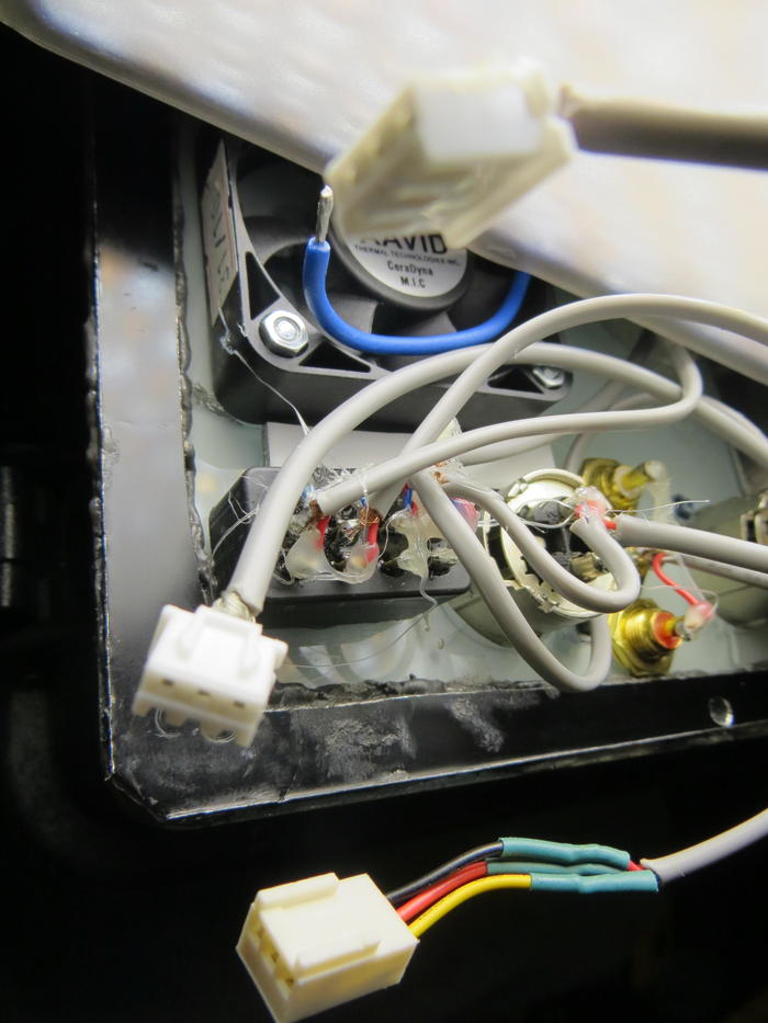
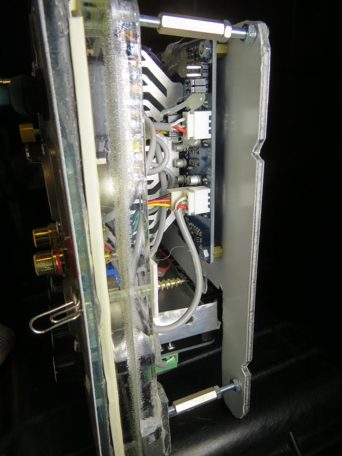
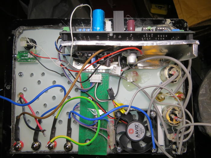
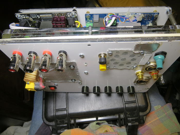
If your not switching between balanced and unbalanced input then put the jumpers into SE position. if you want both input types use a 3 pole switch. which is what i do. theres some photos of my projects here:
#mytechproject
scroll back to the peli case amp builds there might be some photos where you can see some of what i have done.
For my tpa3250 amp i was given cables for it. If your ordering multiple amps in one order, ask for cables for each one.
This is my tpa3255 build, where i made my own cables for the jst-xh connectors:
theres pros and cons., screw terminals mean no extra bits needed, snag is its a pain to disconnect and reconnect all the time during a build. Can so be fiddly to use depending on wire thickness. Where’s jst-xh is fiddly to solder plugs but means its quicker to swap boards or disconnect and reconnect a lot. Its also compact as theres no wires sticking out sideways. If you get ready made cables then its plug and play once ya soldered them to your preferred audio input connectors, unless you get them with the audio connectors already soldered on.
Last edited:
...
There is a 3255 evm clone from the china stores at about $57 I will be picking one up hopefully it is a match for the EVM which costs more and is harder to get. Like you I wish the opamps were socketed... is it hard to solder SOIC?
The china boards compete with each other on low price and noting else. That said the board you point to seems to be a nice clean board. How it sounds - no idea.
Hand soldering SOIC is medium hard, de-soldering is worse. See this video for a smart way YouTube
Soldering SOIC is primarily a matter of not tearing off the small PCB pads. If they are damaged it is really difficult. They stand very little physical force before they leave the board because they are so small.
I always cut the defect IC out with a very fine and pointed cutter, one lead at a time and as close to the IC body as possible. When all leads have been cut the IC body can be removed. Then, the leads can be removed one by one with a soldering iron. Before I continue, I clean the board with a bit of alcohol where the chip was sitting.
Mounting is impossible lead by lead for the smallest IC's but there is a trick to be used:
* Use a fine soldering tip.
* Place the new IC on top of the PCB pads (make sure the IC is turned correctly!) and align it with the pads (take good time to do it well). Hold the chip in place with a match-stick or similar.
* Put a small drop of solder tin on the soldering iron tip and fix the IC to the PCB pads in one of the four corners with the tin drop (it is not a problem if more leads are shorted by the tin in that corner).
* Check that the IC alignment with the PCB pads is still perfect (later you can do nothing about it but start all over again!).
* If the alignment is fine, fix some IC leads in the opposite corner to the PCB pads with another drop of tin (shorts are not a problem).
* Check the IC alignment (absolutely last chance!);
* Fix the IC in the two last corners with solder tin.
* Solder all leads to the PCB pads on one side of the IC with amble solder wire such that many leads on that side are shorted.
* Solder all leads to the PCB pads on the other side of the IC with amble solder wire such that many leads on that side are also shorted.
* Now, the IC is in place but with too much solder tin and many IC leads shorted. Here comes the trick:
* Turn the board around such that the IC is turned downwards but at an angle such that the solder tin would fall off the board and away from the IC body if liquefied.
* Put a bit of solder tin on the tip and run the solder tip along all leads on one side of the IC. With a bit of luck a drop is formed on the solder tip that pulls away all excessive tin from between the IC leads. Also, move the solder tip away from the IC body such that the solder drop is removed from the IC leads. With a bit of luck it will leave a surprisingly good result.
* When the first side has been successfully done and has cooled, do the same for the other side.
* Clean the IC and leads well with alcohol.
* Check with a magnifying glass that no shorts between the leads remain and that the solderings seem fine.
At least, this method has worked well for me.
Sorry, this is more a general working method than a class D issue but it closely relates to the question raised above.
Last edited:
Soldering SOIC is primarily a matter of not tearing off the small PCB pads. If they are damaged it is really difficult. They stand very little physical force before they leave the board because they are so small.
I always cut the defect IC out with a very fine and pointed cutter, one lead at a time and as close to the IC body as possible. When all leads have been cut the IC body can be removed. Then, the leads can be removed one by one with a soldering iron. Before I continue, I clean the board with a bit of alcohol where the chip was sitting.
Mounting is impossible lead by lead for the smallest IC's but there is a trick to be used:
* Use a fine soldering tip.
* Place the new IC on top of the PCB pads (make sure the IC is turned correctly!) and align it with the pads (take good time to do it well). Hold the chip in place with a match-stick or similar.
* Put a small drop of solder tin on the soldering iron tip and fix the IC to the PCB pads in one of the four corners with the tin drop (it is not a problem if more leads are shorted by the tin in that corner).
* Check that the IC alignment with the PCB pads is still perfect (later you can do nothing about it but start all over again!).
* If the alignment is fine, fix some IC leads in the opposite corner to the PCB pads with another drop of tin (shorts are not a problem).
* Check the IC alignment (absolutely last chance!);
* Fix the IC in the two last corners with solder tin.
* Solder all leads to the PCB pads on one side of the IC with amble solder wire such that many leads on that side are shorted.
* Solder all leads to the PCB pads on the other side of the IC with amble solder wire such that many leads on that side are also shorted.
* Now, the IC is in place but with too much solder tin and many IC leads shorted. Here comes the trick:
* Turn the board around such that the IC is turned downwards but at an angle such that the solder tin would fall off the board and away from the IC body if liquefied.
* Put a bit of solder tin on the tip and run the solder tip along all leads on one side of the IC. With a bit of luck a drop is formed on the solder tip that pulls away all excessive tin from between the IC leads. Also, move the solder tip away from the IC body such that the solder drop is removed from the IC leads. With a bit of luck it will leave a surprisingly good result.
* When the first side has been successfully done and has cooled, do the same for the other side.
* Clean the IC and leads well with alcohol.
* Check with a magnifying glass that no shorts between the leads remain and that the solderings seem fine.
At least, this method has worked well for me.
Sorry, this is more a general working method than a class D issue but it closely relates to the question raised above.
I've soldered tons of SOIC (and even TQFP!) and I've never had to have such an long list of steps even on the first go :
My advice is to use a flat head 1.6mm tip OR get a hot air station and some solder paste.
The trick is to coat the pads with solder then place the chip on it or if you prefer you can apply a bit of glue to seat it in place. Then with your 1.6mm tip put the tip on the pin and when it melts pull it outwards away from the chip and it will solder well. Preferably you can push it down so the chip seats level.
PS : I've damaged more through hole than I did SMD.
Last edited:

Potentiometer FX502PRO
Hello everybody,
I am new here and this is my first post. I am absolutely new in DIY and started of just very recently 🙂
I came across this tread and thought I gave this FX-audio FX502PRO a try. The first impressions are favorable, but I am not really blown away.
My daily driver is a DIY TA2020 I listen to now for a few years (an assembled kit I purchased some years ago)
and more recently a HLLY TAMP-90 which I really like. maybe some opamp rolling is an Idea? (I heard the OPA1692 or LME49720NA are a good match)
can somebody tell me what the difference are between the different opamps?
Anyway the main reason I post this message is a issue I have with the FX502PRO,
the pot-meter (volume/gain) is extremely sensitive. At 3 O'clock it is loud! and it's very difficult to adjust it to normal listening levels.
Has more of you have this issue?
kind regards from Sebastiaan 🙂
To turn it around, both these OP-AMPs are high performance audio OP-AMPs. You cannot mention any technical characteristic that unambiguously makes one better than the other. It is a matter of subjective impression of the sound. Perhaps price and availability may be more decisive? Anyway, you can study the datasheets for the differences.
For the potentiometer, it sound like it is bad. Do both channels behave the same? If the sound increases rapidly between 2 o'clock and 4 o'clock, it is not as it is supposed to be.
If you have a multimeter, disconnect the power supply and measure the impedance from one of the outer potentiometer terminals to the slider terminal (mid) - does the impedance change rapidly around 3 o'clock? The same for both channels?
Groetjes,
Last edited:
At 12:00 you're at 20% of output with audiopot ??? so from 12:00 to 17:00 you go as fast from 20% to 100% as from 0% to 20%.
As I understand all FX502PRO have this issue with volume knob. It's need to make some mod for this amplifier. Maybe replace the potentiometer? Any recommendations?
TPA3116 at 24V is not 10% distortion. Nowhere close. At about 25W, it is less than 0.1% for the lower frequencies and about 0.05% for 20K.
That is right before the onset of distortion however.
...
I wrote 21v. Which is the recommended voltage for keeping things safe. Data was from original spec sheet. I also mentioned 8ohm, for 4ohm it gives more power. Do not remember this 100%, been a while since I posted that.
Strongbow60 and impuls60:
I think the filters in those xtz speakers sucks a lot of current. The TPA3250 is not suited for that load.
Thank you for the replies! 🙂
Sorry where I said 3 O'clock, I meant 9 O'clock.
@FauxFrench,
That is too bad 🙁 Yes the sound increases rapidly between 2 o'clock and 4 o'clock, like you said.
What I can hear the the channels are in balans though.
I am a little hesitant to opening the unit for now, maybe I want to check with the seller at aliexpress,
not that I expect much (that is little bit the risk of buying at aliexpress, when things are not all okay)
Besides that I don't know how to handle a multimeter that well (being the total beginner that I am)
I checked the pot-meter with the one of mine passive preamp, and the volume increases also very quickly on preamp.
So maybe it is not that bad. the pot-meter of my passive is a little better, but also increases very rapidly more so then experience with other amps, like the TAMP-90
so maybe it has something to do with the amp design, in relation with my speaker?
They are fairly sensitive (I lost the spec ages ago) a pair of vision acoustique evasion (6 ohm at 89 db if I am not mistaken)
Is there a decrease in sound quality when using two pot-meters? (one of the power amp and and passive preamp) the preamp has a blue alps 50K potential meter,
in between the amp en passive preamp I have a Yaqin tube buffer.
Perhaps... use a smaller pot and reduce the gain?As I understand all FX502PRO have this issue with volume knob. It's need to make some mod for this amplifier. Maybe replace the potentiometer? Any recommendations?
I wrote 21v. Which is the recommended voltage for keeping things safe. Data was from original spec sheet. I also mentioned 8ohm, for 4ohm it gives more power. Do not remember this 100%, been a while since I posted that.
Strongbow60 and impuls60:
I think the filters in those xtz speakers sucks a lot of current. The TPA3250 is not suited for that load.
Datasheet is quoted at 24v and 8 ohms. 🙂
Thank you for the replies! 🙂
Sorry where I said 3 O'clock, I meant 9 O'clock.
@FauxFrench,
That is too bad 🙁 Yes the sound increases rapidly between 2 o'clock and 4 o'clock, like you said.
What I can hear the the channels are in balans though.
I am a little hesitant to opening the unit for now, maybe I want to check with the seller at aliexpress,
not that I expect much (that is little bit the risk of buying at aliexpress, when things are not all okay)
Besides that I don't know how to handle a multimeter that well (being the total beginner that I am)
If the sudden volume increase is around 9 o'clock (and not 3 o'clock) it may be because they have used a linear potentiometer where it should be logarithmic for a more smooth increase of volume.
You cannot hear the difference between one and two potentiometers with respect to distortion.
If you do not feel sure opening the amplifier, keep it closed and use another potentiometer at the input (such as in a pre-amplifier).
- Home
- Amplifiers
- Class D
- TPA3250 somebody is listening?