Hello everyone,
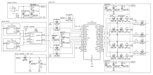
This is my first audio project. Last few days I have been putting together a schematic as well as a BOM for a TPA3128D2 based class D amplifier. Most of the design is taken from the TPA3128D2 datasheet "Typical Application" at page 23 and TPA3116D2 EVM User's Guide (Rev. B) "TPS3116D2EVM Schematic" at page 5 as it is the same as TPA3128D2 Evaluation Module, but includes the schematic and the PCB layers are more readable. I have also included the anti-pop from 360customs and volume control that follows wiring shown in the attached image. The materials of different capacitors are determined by what I gathered from reading through different forum posts.
I am attaching my unfinished schematic. I have multiple questions regarding the design, but I am going to address them one by one in different posts in this thread. What I want to open this discussion with is whether the EMI C-RC snubber (see attached image) is necessary and what is the advantage of including one. Is the advantage audible?
To give you more insight the power supply used is 24V 6.5A, gain is set to 26dB and the speakers are a pair of older 35W 4ohm Pioneer S-P170's.
For the initial post this I believe should suffice, I would like to keep it concise so that it does not deter one from reading the post. Thank you to everyone for reading and responding.
Attachments


Update:
I have found this Class-D Output Snubber Design Guide and it states:
"An output snubber is an RC network placed at the output of a switching audio amplifier. The snubber
dampens any ringing or overshoot on the PWM output waveform. The stray inductance in the IC leads, IC
bond wires, and PCB traces causes the overshoot and ringing. Having an output snubber provides a low-
impedance drainage path to ground for the energy stored in these inductances. Without a provided path,
the stored current finds a path through parasitic capacitance on the PCB and causes the overshoot and
ringing."
However I am not sure whether the output snubber discussed in the linked design guide is not just the bootstrap snubber from my schematic attached in the initial post. Can someone confirm or deny my assumption?
Update:
After discussing my question with someone more educated in this field than I am I have arrived at a conclusion that the EMI C-RC snubber is unnecessary when I use the bootstrap snubber on outputs.
I have also decided to remove the C-RC snubber that I had on the DC power input. I have attached the updated schematic. As of right now I am finished with the schematic and I will be moving to laying out the pcb. Wish me luck.
I have one more question regarding the output impedance. From what I gathered the output impedance depends on the LC filter values. Can I roughly estimate the output impedance using Z = SQRT(L/C)? Example: I want to spec the amplifier to 6ohm speaker, so I would choose L=10uH, C=0.27uF resulting in Z = SQRT(10/0.27) = 6.08ohm. Would that be correct? Would than even be necessary, or is it perfectly fine to drive a 6ohm speaker with the same LC filter that is spec'd for a 4ohm load?
Attachments

Last edited:
Grossly your assumption for impedance matched output filter is correct.
An LC-tank damped with R=sqrt(L/C) is aperiodically dampened - theoretically.
Looking deeper inside, this hole attempt is flaky,
because it is based on the false assumption
of a pure resistive load dampening the LC resonance,
with a frequency peak usually located in the region of 50kHz.
And that is where my concerns come in:
You cannot expect your speakers providing an impedance
close to 4 or 8 Ohms at a frequency of 50kHz.
Period.
So under real world conditions this resonant tank always is under-dampened.
Depending of the impedance curve of your speakers,
frequency response may rise or fall beginning at about 10kHz
with max deviation from linear frequency response of several dB at 20kHz.
Based on a simple LTSpice simulation this can be demonstrated.
Perhaps you like to fiddle with some LC-values while measuring frequency response.
Considering the rising impedance vs frequency of most speakers,
I would prefer to measure unloaded output.
In general this problem can be addressed to some extent applying postfilter feedback.
For details search in this forum "differentiating postfilter",
The superior solution are the self-oscillating class-D-amps introduced by Bruno Putzeys.
Last edited:
