hii the pcb loookks yummy, could you email that file i also have the same chips ,but not enough time to dot he pcb,i dont know how much space is there in that 470 on output side but some time wiht a 8ohms for lower low limit like 1000ufd or 2200ufd calulate f=root of ( 2* 22/7 * R* C) where r is speaker and c is caps and f is the frequency wanted,
I will make the board now and test it if it works good. If it does work good I send you the pcb layout file.
Regards,
Simon H.A.
Regards,
Simon H.A.
Update on the board.
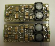
It works perfectly, no clicking and hizzing sound on high volume, no noise at all when not playing. It plays very loud of such a little chip.
I took some pictures of the board.
Regards,
Simon H.A.
It works perfectly, no clicking and hizzing sound on high volume, no noise at all when not playing. It plays very loud of such a little chip.
I took some pictures of the board.
Regards,
Simon H.A.
Attachments
Update on the board.
It works perfectly, no clicking and hizzing sound on high volume, no noise at all when not playing. It plays very loud of such a little chip.
I took some pictures of the board.
Regards,
Simon H.A.
hiii
hows the amp working, does it feel like 15 + 15 or if you bridge it does it fell like 30W ... i m waiting for the pcb
the amp works great. I feel it's really putting some power out. At my school we used it for music and it got good bass and can play our whole classroom up with loud music, and that is only one channel.
I haven't tried it in bridged mode yet, I just need to be sure of how you do it. Isn't it where you use a opamp to make an inverted and non-inverted input for each channel?
Regards,
Simon H.A.
I haven't tried it in bridged mode yet, I just need to be sure of how you do it. Isn't it where you use a opamp to make an inverted and non-inverted input for each channel?
Regards,
Simon H.A.
Isn't it where you use a opamp to make an inverted and non-inverted input for each channel?
Basically, yes. Take a look at the link below for a circuit and good description.....
Bridging Adapter For Power Amps
I used a DRV134, but a good FET input opamp probably would have been a better choice.
Attachments
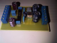
Nice layout! 😀😀😀
It almost looks like I knew what I was doing huh? I can assure you I really don't have a clue.
My understanding of electronics is very rudimentary (at best). I would compare it to how a young child can talk, but doesn't really understand how language works.
I don't know if he did the layout from scratch, but it's not only the cut free ground plane, the chip capacitors soldered directly across IC pins also count on my opinion 😉 I tend to do high power prototypes much in the same way.
It's overkill for such a small amplifier, but I'm used to see the opposite... Something intended to be class D and hi-fi should have that kind of layout anyway, parasitics always make things not work as expected 😉
It's overkill for such a small amplifier, but I'm used to see the opposite... Something intended to be class D and hi-fi should have that kind of layout anyway, parasitics always make things not work as expected 😉
I don't know if he did the layout from scratch....
Of course I did!!!
hey how about sharring the pcb file...looks cool
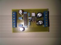
Sorry, but I don't have any PCB files to share since I don't do things in a traditional way. It is highly tailored to my specific DIY PCB making methods.
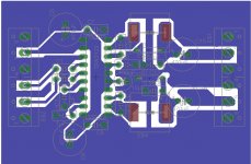
I will attach a PDF with a similar layout minus the DRV134 (I deleted the DRV one I think). You can use this for a single ended stereo board but will need to add the output capacitors externally.
Please don't ask me what goes where or the values; I didn't make the layout to be stranger friendly. 😉
Attachments
In the beginning I did things that way too, no schematics, component values more or less from memory, or looking at the datasheets on the fly, or calculating things on the fly as you solder them. My PCB files had no data on components too...
Now I'm designing stuff that is going to be mass produced and the amplifier in which I'm working has around 500 parts. Obviously I had to change my methods a bit... Leaving some documentation about what you do is always useful 😉 Now I even have text files with change logs and lists of ideas that I have to write as they come (to avoid the risk of forgetting something useful).
Those people desperately asking for ready made files may want them for mass production too. That's what I don't like about people asking for complete design files for free... Not very DIY...
Well, you are a pro Eva; one of the best. I am just a tinkerer, and I'm fine with that.
My component choices might not make much sense to some, but that's because I always compromise between what part is best and what components I have on hand. I don't like to buy new parts if I don't have to.
Take for instance the insane amount of 1uF 100V XR7 ceramics caps I used on my boards. I have ~3000pcs of these, so why not use them if I can. 🙂
I am interested in using your design. Would you recommend the design you posted and if so, would you attach the eaglefiles?I get it all now how it works.
I have created a new layout and I will try make it and just cross my fingers for that it is stable.
Thank you!
It works just fine. I can create the board and post a video of it?
Edit: And yes, I might be able to get the eagle files, and yes I would recommend it. Might need a bit changes in the design for better connection abilities.
Regards,
Simon H.A.
Edit: And yes, I might be able to get the eagle files, and yes I would recommend it. Might need a bit changes in the design for better connection abilities.
Regards,
Simon H.A.
I would say;
Zip/rar/7z the eagle (and pdf) files and attach it in a reply. I and I think many others would be interested.
Zip/rar/7z the eagle (and pdf) files and attach it in a reply. I and I think many others would be interested.
I received the pcb layout and after altering it a bit (connector size, pin distance etc) I etched the board and put it together. However, I seem to be having some 50 or 100Hz noise on the output.The amp works, but there is some humming. I have all the 100N caps and local (power) decoupling. Where should I be looking for problems? I have no >12V battery available and have not lab psu.
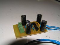
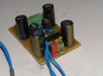
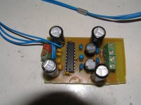
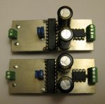
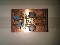
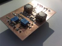
Hi, here are some pics! The PCB layout is not 100% made by me. I just altered some spacing to try the design. (As you can see I changed it not enough since I had to put components on the bottom instead of on the top.)
The input caps are 1uf.
The big block caps on the right side are 680nF, one on the top, one on the bottom.
The caps "parralel" to the TPA chip, right side, are the 220uF's.
The resistors on the input side are 4k7 (an attempt to make the input more stable/silent).
The resistors on the output side are 4k7 too, according to the datasheet.
Elco's are 470uF for the HF filter and 2* 100uF local decoupling. (I had no larger value in the voltage/grid available).
The center elco is 10uF from analog VCC to gnd.
The input source for testing was an iPod and a CD-player with headphone output. The gain is set to high (will change that later on)
The music plays ok, but when I connect the source, I have humming, with no device I have humming too.
The PSU is a wall wart 15V 0.7 A
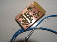
PS. Please don't judge my dodgy soldering. I will use crosshair type of connections to the ground in the future. It is horrible soldering a component to a well heat-conducting surface.
The input caps are 1uf.
The big block caps on the right side are 680nF, one on the top, one on the bottom.
The caps "parralel" to the TPA chip, right side, are the 220uF's.
The resistors on the input side are 4k7 (an attempt to make the input more stable/silent).
The resistors on the output side are 4k7 too, according to the datasheet.
Elco's are 470uF for the HF filter and 2* 100uF local decoupling. (I had no larger value in the voltage/grid available).
The center elco is 10uF from analog VCC to gnd.
The input source for testing was an iPod and a CD-player with headphone output. The gain is set to high (will change that later on)
The music plays ok, but when I connect the source, I have humming, with no device I have humming too.
The PSU is a wall wart 15V 0.7 A
PS. Please don't judge my dodgy soldering. I will use crosshair type of connections to the ground in the future. It is horrible soldering a component to a well heat-conducting surface.
Attachments
Last edited:
- Status
- Not open for further replies.
- Home
- Amplifiers
- Class D
- TPA3122 works fine on battery - starts clicking on powersupply.