I am testing a TPA3122 (Datasheet: http://www.mouser.com/ds/2/405/slos527a-88277.pdf) on my breadboard before designing a PCB for it, and I am having trouble with the output filter. I am powering it from a 12V / 700mA switching wall power supply and the output is bridge tied load (BTL) with an 8 ohm speaker.
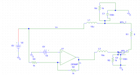
I have connected, on my breadboard, a circuit according to Figure 29. BTL 8-Ω Application Schematic with some changes to the values because I only have certain parts on hand. Actual values are show in the attached file PSPICE_1.png. The battery and op amp are meant to simulate the output signal when muted. The inductors are 2A rated (Jtron 10UH 2A Wirewound Power Inductor - Black (10 PCS) - Free Shipping - DealExtreme) and the capacitors are normal ceramics.
When I power this circuit up on my breadboard, the output does not play any music, and the AVR microcontroller I have monitoring the output shows that the mean voltage is 0V, with occasional spikes to 6 or 7 V. It appears that the amplifier is repeatedly entering shutdown mode whenever it tries to start up. If I remove one of the filter caps, the amplifier starts up just fine, plays sound, and the monitoring uC reports sensible voltages. In order to figure out what's going on, I turned to a PSPICE simulation.
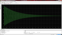
In the simulation, I set the capacitors to an initial voltage of zero. The battey and the op amp are meant to simulate the BTL outputs of the amplifier. I had a VAC in there for frequency analysis, but removed it for this test. I performed a Transient Analysis over an interval of 1ms. A plot of V(BTL_1) is shown in attached file PSPICE_2.
As can be seen, there is enourmous ringing on the output filter at start up, almost 30 kV peak, and lasting for over a millisecond! The plot of I(L1) is no less ridiculous, showing peaks of kiloamps. It seems obvious that this is the cause of the shutdowns.
When I disconnect the capacitor attached to BTL_2 and rerun the Transient Analysis, I get the waveform shown in PSPICE_3. The ringing is still huge, but lasts for a much shorter period of time, only about 60 us. I believe this shorter ringing is what allows the amplifier to start up when one of the capacitors is disconnected.
Now the main question is, how do I tame this? I hooked it up according to the application schematic and it won't work. How can I tame the ringing so that the amplifier works?
I have connected, on my breadboard, a circuit according to Figure 29. BTL 8-Ω Application Schematic with some changes to the values because I only have certain parts on hand. Actual values are show in the attached file PSPICE_1.png. The battery and op amp are meant to simulate the output signal when muted. The inductors are 2A rated (Jtron 10UH 2A Wirewound Power Inductor - Black (10 PCS) - Free Shipping - DealExtreme) and the capacitors are normal ceramics.
When I power this circuit up on my breadboard, the output does not play any music, and the AVR microcontroller I have monitoring the output shows that the mean voltage is 0V, with occasional spikes to 6 or 7 V. It appears that the amplifier is repeatedly entering shutdown mode whenever it tries to start up. If I remove one of the filter caps, the amplifier starts up just fine, plays sound, and the monitoring uC reports sensible voltages. In order to figure out what's going on, I turned to a PSPICE simulation.
In the simulation, I set the capacitors to an initial voltage of zero. The battey and the op amp are meant to simulate the BTL outputs of the amplifier. I had a VAC in there for frequency analysis, but removed it for this test. I performed a Transient Analysis over an interval of 1ms. A plot of V(BTL_1) is shown in attached file PSPICE_2.
As can be seen, there is enourmous ringing on the output filter at start up, almost 30 kV peak, and lasting for over a millisecond! The plot of I(L1) is no less ridiculous, showing peaks of kiloamps. It seems obvious that this is the cause of the shutdowns.
When I disconnect the capacitor attached to BTL_2 and rerun the Transient Analysis, I get the waveform shown in PSPICE_3. The ringing is still huge, but lasts for a much shorter period of time, only about 60 us. I believe this shorter ringing is what allows the amplifier to start up when one of the capacitors is disconnected.
Now the main question is, how do I tame this? I hooked it up according to the application schematic and it won't work. How can I tame the ringing so that the amplifier works?
Attachments
First I am not technical at all. The output filter is supposed to weaken switching frequency in output I believe and the 1k ohm/100nF and 10uH combination has a peak around the switching frequency, so switching frequency in output is even stronger than without this outputfilter. Without the 100nF peakingfrequency is much lower, and filter is surpressing switching frequency a bit. Could that be reason for shutdown???
Something is wrong with your measurement - you can't get that kind of voltage (30kV) out of a TPA chip with a 12v supply - it would fry all the gates like it were ESD and nothing would work. Do you have high speed bypass caps mounted as close to the amp pin Vcc as possible? It should make music even without the output filter. Check to see if the bootstrap caps are still good. If you has high voltages it would ruin those and the amp won't make music due to bad bootstraps.
Hi
Referring to the data sheet, Pin 1 and pin 10 are the V+ supply, your simplified schematic does not show these connections. It is also unusual to have both inputs connected to DC sources
Compare your schematic to Figure 28 and 29 on Page 14 and 15 of the pdf document, and follow those diagrams and pinouts.
Cheers / Chris
I've done numerous frequency sweeps of this filter with PSPICE; the cutoff frequency is around 30 kHz.First I am not technical at all. The output filter is supposed to weaken switching frequency in output I believe and the 1k ohm/100nF and 10uH combination has a peak around the switching frequency, so switching frequency in output is even stronger than without this outputfilter. Without the 100nF peakingfrequency is much lower, and filter is surpressing switching frequency a bit. Could that be reason for shutdown???
Also, the filter works without the caps. When both are present, it fails due to what I suspect is shutdown caused by current overload.
It's not measurement, it's a PSPICE simulation. I'm aware it won't perfectly correspond to reality, it's just a way of trying to figure out what's going on with this output filter that's causing my amp to shutdown. I'm well aware that 30kV is not what's happening on my breadboard, for two reasons: 1) the amp will go into shutdown long before that happens, and 2) I was simulating a pure inductance and a pure capacitance. I added some series resistance to the inductors (0.4 ohms, which I measured) and the simulated ringing is substantially reduced, though still more than enough to put the amp into overload shutdown with both caps on there.Something is wrong with your measurement - you can't get that kind of voltage (30kV) out of a TPA chip with a 12v supply - it would fry all the gates like it were ESD and nothing would work. Do you have high speed bypass caps mounted as close to the amp pin Vcc as possible? It should make music even without the output filter. Check to see if the bootstrap caps are still good. If you has high voltages it would ruin those and the amp won't make music due to bad bootstraps.
The amp is still good; I mentioned that it does work when I remove one of the capacitors from the circuit, and that is still true now.
I don't have a TPA on my schematic, I'm just simulating the outputs of it (muted) with a 6V DC step input into both ends of the filter. My actual board setup did correspond to the Figure I listing in my OP.Hi
Referring to the data sheet, Pin 1 and pin 10 are the V+ supply, your simplified schematic does not show these connections. It is also unusual to have both inputs connected to DC sources
Compare your schematic to Figure 28 and 29 on Page 14 and 15 of the pdf document, and follow those diagrams and pinouts.
Cheers / Chris
I have found an app note (http://www.ti.com/lit/an/sloa119a/sloa119a.pdf) from a different thread that has a different filter setup on page 7 for a traditionally modulated bridge-tied load just like my setup. Instead of two caps to ground, there is one cap across the load speaker. THis setup works on my breadboard. Now I just need to select appropriate values for the filter.
Well if I look at filtersimulator, I read your combined LCR filter creates peaking around 160khz before filtering, Q is very very high for this filter, I understand that means high peaking... so C should be closer to TI suggestion and/or L should be closer to TI suggestion, lowering the R in your filter, it is in your model, to single digit without a k helps too
The ringing output filter is a problem an spice gives an indication of this.
Considering damping it - the damping resistor for aperiodic damping is calculated as R = sqrt(L/C).
Using 10uH and some 100nF Filter you need 3~10 Ohms.
A RC-network of 5R + 0,5uF might fit for this purpose.
Furthermore consider the Blocking capacitors - there ESR adds to the series impedance of the resonant tank. I would recommend some low ESR-Caps quite close to the power supply pins of the chip, refer to TI applications.
You can clamp the resonant tank with Diodes to the supply rails which limits the resonant current excursions - normally not needed.
Or most simply, you omit the output filter using the filterless mode...
Last edited:
- Status
- Not open for further replies.
- Home
- Amplifiers
- Class D
- TPA3122 Class D Amp Ringing on output causing shutdown