Try using a signal divider of two resistors on each input. 1k between(+-) the input and ground (on the board) and a 1k-4.7k series resistor between the board's input(+) and the signal source. By selecting resistors, you set the desired output level.
Use a high-quality power source no more than 16V for a current of at least 3-5A.
Use a high-quality power source no more than 16V for a current of at least 3-5A.
"The mute on power mod also works really well! I used a Schottcky diode put between the mute pin and ground..."
Hi. I know this is an old thread, but I really need assistance.
What value of schottky diode would be used in this particular instance?
Thanks and best wishes
-Chuck
Hi. I know this is an old thread, but I really need assistance.
What value of schottky diode would be used in this particular instance?
Thanks and best wishes
-Chuck
Hello @Chasmo57 , i can't remember the value of the schottky diodes i used, they were bulky ones as it can be seen from pictures, very likely overkill for this application. In THIS THREAD, which is a more elaborate implementation, a NSR0530HT1G Schottky is used; i guess it could work in the simpler one as well, or something with similar specifications.
For gain-setting resistors on TPA3118 (BLUE) PCB:
Can we just stack (up on R28( parallel 39k resistor to get ~20k? Likewise, if one were to stack an 82k resistor onto R28 inn parallel, could we get ~26-27k ohms(rather than removing and replacing)? I am loathe to remove & resolder SMD resistors, (fearing damage to pads)but it seems a simple matter to solder another on top. Thanks & best wishes .
-Chuck
"
My board has a slightly different resistor numbering.
Gain Resistor values..."
Mine is also different from the above boards. Anyone have a similar board and know which is the gain- setting resistor to remove for 20dB gain?
Thanks and best wishes
--Chuck
My board has a slightly different resistor numbering.
Gain Resistor values..."
Mine is also different from the above boards. Anyone have a similar board and know which is the gain- setting resistor to remove for 20dB gain?
Thanks and best wishes
--Chuck
Attachments
I have the pop noise about every second, too.
Before I change the gain resistors, I made a picture with an oscilloscope:
View attachment 1086153
My board has a slightly different resistor numbering.
Gain Resistor values: R1 47k, R2 100k
I plan to bridge R1 with another resistor to get around 20k -> 26dB.
What if R1 is below 20k does that simply reduce the gain further?
View attachment 1086152

Okay.... if using a phone.
I personally plan on using these amps to drive multiamped speakers in a conventional hifi system(Server, DAC/Line amp, electronic crossover) , and my other amps have ~26dB gain. 32dB is way too noisy!
Which two resistors are for gain-setting, and which to remove to quiet it down?
I personally plan on using these amps to drive multiamped speakers in a conventional hifi system(Server, DAC/Line amp, electronic crossover) , and my other amps have ~26dB gain. 32dB is way too noisy!
Which two resistors are for gain-setting, and which to remove to quiet it down?
Last edited:
Okay,
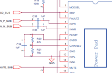
After studying the pinout diagram for the Tpa3118 amp It appears that R11(75k) and R12(47k) on my boards are equivalent to R20(47k) & R21,(75k) in the pinout diagram.
Does this mean I can lower the gain (to 20dB) by removing the 75k resistor(R11)?
Or am I missing something?
Thanks & best wishes.
-Chuck
Attachments
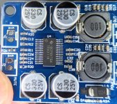
These boards have a counterfeit chip onboard, as you can see from the different pin count compared to the real tpa3118. I have a couple of them but they had a different component layout, so I can't be sure if removing the 75k resistor will reduce the gain; my boards had pin 5 and 6 tied together and those could be connected to ground to lower the gain.Sorry for the duplicate postong above(my phone's acting up)
Anyone out there have same board, or know which resistor to remove for 20 DB gain? Thank you and best wishes.- -Chuck
If the chip has remained the same as mine, then it should be equivalent to a tpa3110, therefore you could check whether pin 5 is connected to ground or not, and Chech which voltage is on pin 5 and pin 6 while the board is on.
If you can bear any background noise, the easier way is to just use a potentiometer at the input. Something like 50kOhm will work.
Last edited:
Yes.Anyone else care to corroborate this claim?
The original tpa3118 has a 32 pin package (see TI datasheet).
The chip in the image of your post #28 has only 28 pins.
Thanks.
It's truly astonishing that sellers are able to freely pass fakes on in the marketplace with no restrictions or repercussions.
Are these tpa3110 useful (decent sounding) or just junk to be tossed out with the trash?
😡
It's truly astonishing that sellers are able to freely pass fakes on in the marketplace with no restrictions or repercussions.
Are these tpa3110 useful (decent sounding) or just junk to be tossed out with the trash?
😡
@Chasmo57 they are decent enough, they still handle 2 ohm loads like the real tpa3118, but they're noisy if you use a couple of them together; if the gain is lowered, the noise is also lowered quite a lot. Can't comment on what power they actually put out as I don't have measuring equipment.
The only advantage I found in these boards is they don't have any power on pop, so no anti-pop circuitry was needed.
The only advantage I found in these boards is they don't have any power on pop, so no anti-pop circuitry was needed.
Motoralbi,
Thank you for the information on the counterfeit chips.
Of particular interest is reducing gain (and therefore noise)- how much reduction of gain would be had if pin 5 or 6 were tied to ground?
Note: The noise level upon power on is really high. Once source is tied it goes away, then comes back at a lower level when my source is muted. Any help here is appreciated.
--Chuck
- Home
- Amplifiers
- Class D
- TPA3118 noise and pop