Ok. So I have been reading through the giant thread on this amp but I have not found what I am looking for yet.
I have the red board version and would like to remove the black power supply connector so that I can extend it when I put this into an case. Does it just pop off? Or is there soldering involved? Or is there a better way to do this?
Thanks
I have the red board version and would like to remove the black power supply connector so that I can extend it when I put this into an case. Does it just pop off? Or is there soldering involved? Or is there a better way to do this?
Thanks
The connector is soldered on. The easy solution is to leave the connector in place and solder power leads where the tabs for the connector stick through the bottom of the board.
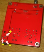
Ok. That makes sense. I have seen this picture with the leads identified. But what kind of power cable do I attach to this? Do I just take a power cord and cut off the end and solder that?
An externally hosted image should be here but it was not working when we last tested it.
I have also seen this pic on the Fleawatt site where he connects it to a connector mounted on the casing. How hard is this?

Ok. That makes sense. I have seen this picture with the leads identified. But what kind of power cable do I attach to this? Do I just take a power cord and cut off the end and solder that?
An externally hosted image should be here but it was not working when we last tested it.
You need to provide 12-22V DC to these keeping the polarity in mind.
Ok. That makes sense. I have seen this picture with the leads identified. But what kind of power cable do I attach to this? Do I just take a power cord and cut off the end and solder that?
An externally hosted image should be here but it was not working when we last tested it.
Comparing this picture to the one you took from Flea Watt, I think your polarity was not assigned properly.
Regards,
Comparing this picture to the one you took from Flea Watt, I think your polarity was not assigned properly.
Regards,
The ground is at both points.
Attachments
The ground is at both points.
KJA,
That's what I thought. The two points that were marked + and - in the picture are actually both ground or -. So if one connect the two together, there will be no power. I was comparing it to the power connection shown in the picture from Fleawatt (post #4).
Regards,
- Status
- Not open for further replies.
- Home
- Amplifiers
- Class D
- tpa3116 newbie build question(s)