I now have LTXVII so I have checked the latest files. The 17k in last post had several supply voltages to opamps wrongly labelled so I include the update.
Attached 17L files which uses independent Class-G lift. The previous 17k version used common rail lift. It saved 4 MOSFETs but has a problem when one channel output is shorted -- the shorted channel gets rail lifted when the other non-shorted channel needs lift, and this defeats the advantage of Class-G for reduced SOA when the output is shorted. So independent Class-G lift is used in the 17L version. The full circuit is shown below

A hi-res zoom-able PDF version is attached.
It looks complicated but is for 2 channels and is modular -- as two PCB's, plus two power supply Class-G modulators, and one power transformer. Each PCB (Post 318) has two pair of power transistors for 13A peaks intended for 8 Ohm loudspeakers with 5 Ohm impedance dips. Each PCB includes the input level shift (aka VAS) and the bias centering stage using an opamp (bottom right) for DC input (but normally decoupled with a capacitor).
Attached 17L files which uses independent Class-G lift. The previous 17k version used common rail lift. It saved 4 MOSFETs but has a problem when one channel output is shorted -- the shorted channel gets rail lifted when the other non-shorted channel needs lift, and this defeats the advantage of Class-G for reduced SOA when the output is shorted. So independent Class-G lift is used in the 17L version. The full circuit is shown below
A hi-res zoom-able PDF version is attached.
It looks complicated but is for 2 channels and is modular -- as two PCB's, plus two power supply Class-G modulators, and one power transformer. Each PCB (Post 318) has two pair of power transistors for 13A peaks intended for 8 Ohm loudspeakers with 5 Ohm impedance dips. Each PCB includes the input level shift (aka VAS) and the bias centering stage using an opamp (bottom right) for DC input (but normally decoupled with a capacitor).
Attachments
Last edited:

It's interesting to see a different power amplifier schematic.
In the PDF version it isn't clear on the wire crossings which connections are made and which are not. For example on the LT Spice schematic R172 doesn't connect to R166 but R162 and R166 do connect. But on the PDF reader that I am using R162 and R166 are shown disconnected, the dot showing a connection has been missed.
I haven't looked in detail but what are the differences between the 4 different amplifier schematics? Is there overall feedback from the outputs?
Hi PChi,
Nice to see someone with interest in "a different power amplifier schematic".
Anyone new to this thread should look at Post 1 which has a summary so far of the variations I have looked at and tried.
The latest Class-G above is Topology 2 and is in progress for bench testing.
Re: PDF schematic.
I have an updated PDF attached to fix the ambiguity of wire crossings. Thanks for mentioning it. I'd assumed most could load the schematic into LTspice to view it, being too large for a hires jpeg picture insert. Maybe there are many who can't use LTspice for viewing? Like MAC users? Etc?
Re: Peak current requirements for driving "difficult" loudspeakers (I mention it in earlier posts):
See the PDF attached of measurements of peak currents with music by Keith Howard in HiFi News.
He did not find any evidence for the need for driving 2x peak current levels (or 4x!!) due to loudspeaker impedance dips with music signals.
So I am thinking it is OK to use peak levels only 30% higher than for nominal 8 Ohm systems (most modern power amp design books say amps need to deliver 2 times to 4 times normal peak currents).
These assumed levels affect the number of parallel output pairs needed as well as power supply ratings -- and therefore the amplifier's cost and weight.
BTW My apology for the poor PDF quality - it's mainly due to a low quality library photo-copier.
Attachments
Thanks for modifying the schematic so that the PDF connections are obvious.
I tried to run the simulations
Autobias-ES3BB-MJL3281-OPA1656-2slice-ZXT851-shift-DCin-2Bridge2x8R-PS+G-1v3k.asc
Autobias-ES3BB-MJL3281-OPA1656-2slice-ZXT851-shift-DCin-2Bridge2x8R-PS+G-1v3L.asc
But OPA 1656 sub circuit names aren't the same as in the file level_3a_.sub. I was able to get the simulation to run after changing the names to level_3a_
Autobias-ES3BB-MJL3281-OPA1656-2slice-ZXT851-shift-DCin-2Bridge2x8R-PS+G-17k.asc works and produces a result.
Autobias-ES3BB-MJL3281-OPA1656-2slice-ZXT851-shift-DCin-2Bridge2x8R-PS+G-17L.asc for me sticks at Transient Analysis 08.0% done.
I am guessing that some of the perceived issues with power amplifier output current may have been due to premature operation of output power transistor safe operating area protection circuits when driving loudspeakers. I think that testing with a variety of loads including a dummy loudspeaker (IHF-A-202 1978) is a good idea.
HiPchi,
Nice to see you got one running in LTspice. I assume you are using LT-XVII or later. The files ...17k.asc are for LT-XVII or later. So the first 2 files you modified are not for your LT version - only for LT-IV - because they renamed the Level.3a.sub in LT-IV to Level_3a.sub in LT-XVII and later - throwing "a spanner in the works" as we can all see here😵.
Re: Stalling at 8 ms.
I use the Alternate solver engine. Try changing it:
Open the Control Panel (icon with the hammer) under SPICE>Engine>Solver tab select Alternate.
Re: Testing with dummy loudspeaker loads is a good idea. I had been thinking of finding one. AFAICS low impedance dips in "difficult" loudspeakers seems to be from a crossover interaction and not the speaker drivers. So a loudspeaker model needs more than just a single speaker driver model, it needs all the crossover components as well. Anyone here got a complete model they can share?
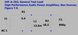
BTW the IHF-A-202 seems to be for a 20ms sine burst twice a second. It would be a useful test for this amp. I notice it was used for the Crest 8001.
Nice to see you got one running in LTspice. I assume you are using LT-XVII or later. The files ...17k.asc are for LT-XVII or later. So the first 2 files you modified are not for your LT version - only for LT-IV - because they renamed the Level.3a.sub in LT-IV to Level_3a.sub in LT-XVII and later - throwing "a spanner in the works" as we can all see here😵.
Re: Stalling at 8 ms.
I use the Alternate solver engine. Try changing it:
Open the Control Panel (icon with the hammer) under SPICE>Engine>Solver tab select Alternate.
Re: Testing with dummy loudspeaker loads is a good idea. I had been thinking of finding one. AFAICS low impedance dips in "difficult" loudspeakers seems to be from a crossover interaction and not the speaker drivers. So a loudspeaker model needs more than just a single speaker driver model, it needs all the crossover components as well. Anyone here got a complete model they can share?
BTW the IHF-A-202 seems to be for a 20ms sine burst twice a second. It would be a useful test for this amp. I notice it was used for the Crest 8001.
Hi All,
Attached is a sim with 3 step Class-G. It improves max efficiency with music to 50%. Recall Crest 8001 is 2 step-G with music or 1/3rd power is 31% max.
To get 3 voltage levels at 33%, 66%, 100%, I add a full-wave doubler giving 140V no load, sagging under load to about 110V peak to the power amp, giving about 1600W/8R peaks per channel (but not suitable for continuous sinewaves with the transformer rating and capacitors used here). To build it, I'd lower the secondary voltage slightly to say 30V FL and use lower cost 50V caps. See snip below. View the PDF for the circuit or zip run it.

Since the full wave doubler takes 80ms at startup to reach full voltage I have delayed the music recording by 80ms (a different wave file file to previous sims).
Attached is a sim with 3 step Class-G. It improves max efficiency with music to 50%. Recall Crest 8001 is 2 step-G with music or 1/3rd power is 31% max.
To get 3 voltage levels at 33%, 66%, 100%, I add a full-wave doubler giving 140V no load, sagging under load to about 110V peak to the power amp, giving about 1600W/8R peaks per channel (but not suitable for continuous sinewaves with the transformer rating and capacitors used here). To build it, I'd lower the secondary voltage slightly to say 30V FL and use lower cost 50V caps. See snip below. View the PDF for the circuit or zip run it.
Since the full wave doubler takes 80ms at startup to reach full voltage I have delayed the music recording by 80ms (a different wave file file to previous sims).
Attachments
On IHF-A-202 I believe that IHF is the American Institute of High Fidelity and the standard is 'Methods of Measurement for Audio Amplifiers'. I don't have a copy of the standard (which appears to have been superseded) but it was described in the magazine Elektor, issue January 1979. It specifies a reactive (dummy loudspeaker load) that I used. It also specifies a tone burst among other tests.
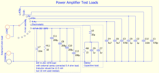
I have also attached a circuit diagram of the load that I built. The different loads are selected using a wire link that plugs into 4 mm sockets. A rotary switch would be preferable but any high current parts that I found were rare and expensive so I used 4 mm sockets and a link. There are some spare sockets for any additional loads that may be added.
The circuit is used in conjunction with a load that also uses wire links and sockets to select the resistance from 0 to 9.9 ohms in 0.1 ohm steps.
Any suggestions on what other dummy loads could be used are welcome. It would be useful to have an agreed standard to compare amplifiers.
Attachments
- Home
- Amplifiers
- Solid State
- Towards a wideband non switching Auto Bias power amp