Do you see any improvement in simulation?
Yes: it does not latch up.
HF stability is still... an interesting question.
Everyone seem to think autobias is awesome ; I would certainly like having such a circuit (it it worked)... so I'm going to play devil's advocate and defend the classic solution. That's not arguing for the sake of arguing or nitpicking: the purpose of the devil's advocate is to point out the flaws in your design to help you improve it.
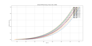
MOSFETs still have wide variations in the wingspread curves with junction temperature changes due to music power variations. Also startup of amp.
Tj only changes threshold voltage (see attached graphs), so changes in temperature are equivalent to changes in bias current setting of the amplifier. Since there is no gm-doubling with FETs using reasonably low source resistor values (<=0R15) and bias current, bias drifting higher when it gets hot isn't a problem: on the contrary, it reduces crossover distortion.
Placing the temperature sensor on the center pin of TO-247 package, which is internally connected to leadframe, eliminates most problems with the standard Vbe-multiplier. Bias settles in a few seconds and it is stable, even in the worst case, which is bipolars without any emitter resistors. It will work with vertical MOSFETs, no doubt.
Further, a bias controller removes the necessity for the bias trimpot.
True, that's convenient, but if you need a pair of THAT300 matched transistors per channel, at €20 each, that convenience is a luxury. So if you replace them with cheaper dual matched pairs like BCM847 there will be mismatch between pairs and you will need a pot 😀
Besides, an idea I want to try is automatic bias setting: if an amplifier is powered several hours per day, but it is not playing music all the time, then over the years, cost of electricity for a high bias setting becomes significant, perhaps higher than the cost of parts for the amplifier. So, a circuit that automatically reduces bias to a very low level when there is no music would allow a much higher bias when actually playing music, for the same electricity cost. And it gives warms and fuzzies for saving the planet. So that would mean not one bias pot, but two or three, depending on setting: idle/youtube videos/audiophile, etc
An autobias circuit would be ideal for this, because it eliminates the thermal lag at power-up. But putting the sensor on the collector/drain pin makes the bias settle in a few seconds, so it's equivalent.
And one more. Variations in the MOSFET's p/n (mis)match don't matter much. The controller loop feedback removes most of these at the lower frequencies (like the 1-3kHz region).
Yes, but... that's the same as adding more feedback to the whole amp, which is easier to get stable, because the components in the feedback loop work at known operating points, so their behavior is pretty stable and known, whereas the BJTs in the autobias nonlinear feedback loop operate over the whole range of Ie and gm, which means their characteristics (fT, phase shift etc) vary wildly.
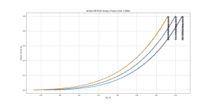
In fact, even with power BJT's controllers give almost the same wingspread plot (singular), which becomes a generic curve (it hardly changes once you pick the source resistor value).
Yes it gives the textbook perfect crossover of BJTs without emitter resistors.
However this crossover can also be achieved by using... BJTs without emitter resistors... So it's like... why emulate it when you can actually have it? What an autobias would do is eliminate turnoff spikes completely though.
Note it is only "perfect" when bias current is high enough. At low bias currents (<50mA) it is worse than with emitter resistors. So autobias won't save power.
Attachments
AutoBias2
I'm sorry, but AFAIK, there is no reference implementation and if there was one, building it would be still rather tricky, in particular with regard to HF stability and overload conditions. So, I'm afraid the AutoBias2 circuit doesn't lend itself to a "quick and dirty" evaluation.
Cheer, E.
Hi peufeu,Nice, that solves the issue.
Is there a reference implementation somewhere? I would like to build one to compare to resistor-free BJTs, but I would rather not spend too much time on stability issues.
I'm sorry, but AFAIK, there is no reference implementation and if there was one, building it would be still rather tricky, in particular with regard to HF stability and overload conditions. So, I'm afraid the AutoBias2 circuit doesn't lend itself to a "quick and dirty" evaluation.
Cheer, E.
I've tried it years ago (including a slew limitation circuit, I still have some PCBs) and it was a pretty frustrating and expensive total failure. It was impossible to stabilize this autobias circuit under practical conditions (overloading, step response, etc...). The circuit presented appears as a good idea, a great simulation exercise, but otherwise it is useless from any practical perspective. A good lesson to learn for those that believe in designing by simulation only.
Last edited:
BTW did you try the LT1166, or any other discrete types? We'd love to hear any problems or success(s).
Sorry, I can't help you with that. I only designed and built two audio power amplifiers. The first was a variant on the Blomley design. My variant didn't work well: I got it to produce music, but the next time I switched it on the emitter resistors incinerated. The second is the one that was later published in Electronics World February 1996.
The latter one was really a combination of things I had learned at the Delft University of Technology, with a few details of my own. There were these two amplifier professors, Ernst Nordholt, a Buddhist who liked to take a holistic view on amplifier design and came up with a systematic approach to near-optimal design of amplifiers, particularly rather unconventional low-level class A amplifiers (LNAs, phono amplifiers, amplifiers for transducers, that sort of thing). The other was a Christian called Johan Huijsing who was very creative and very much into op-amps and class-AB bias loops. In 1976, he and Frans Tol were the first to publish a class-AB bias loop as far as I know. The story goes that Nordholt and Huijsing never agreed on anything, but I learned a lot from both of them.
Last edited:
Hi peufeu,...Everyone seem to think autobias is awesome ; I would certainly like having such a circuit (it it worked)... so I'm going to play devil's advocate and defend the classic solution. That's not arguing for the sake of arguing or nitpicking: the purpose of the devil's advocate is to point out the flaws in your design to help you improve it. ...
Thanks. Your cases for the classical solution are sound. Most of my reasons for auto bias don't stand cross examination.
The issue with the classical bias sensor is after a prolonged loud section once the heatsink is hot, the Tj falls fast (like 100ms) but the bias sensor is delayed, for most sensors by many 10's of seconds, and some several minutes. This results in a drop in bias current and if the bias was already quite low (some like it like that) then the distortion can skyrocket with a low bias for the delay period.
The heat up delay is not an issue as you point out because the bias sensor delay it results a short term increase in bias which doesn't create much extra distortion.
I agree, if the bias sensor delay can be brought to a second or two then the argument for auto bias to overcome thermal lag distortion doesn't hold weight. IIRC Bob Cordell showed ThermalTrak's response time was in the 200ms to 500ms range (tracking to say 50% of final).
Your method of soldering a sensor to a leg of the power transistor gives a fast enough response and is not too hard for DIY amps. I bought some SMD thermistors for this but I haven't go around to trying them yet. They offer a wide range of temp-cos using series and/or parallel combinations of two thermistors.
Even if the delay is reduced to a second or so there is still the issue of local thermal runaway with no emitter resistors or small values (same with MOSFETs but less so due to their lower gm). As per Bob Cordell's calculations eg here. It depends on the transistors Vce (or Vds). Cascoding can prevent this, also stacking reduces each Vce, or using two amps in a bridge (to get the same power you halve the supply rail voltage so Vce is halved).
------
My interest in simulating auto bias loops was after analysis of Bob Cordell's DoubleCross section in his 2nd Edition. DoubleCross seemed to reduce the distortion in the first watt zone to about 100 times lower than classical output stages. But this distortion null cannot be maintained when the transistor temperatures change during normal use. So I thought why not look at using auto bias with DoubleCross? I had never used them before in an amp or simulated them.
After a month of simulations of 3 types: the LT1166, Class-i and Edmond Stuarts AutoBias2 -- What I found is that auto bias can give similar low distortion to DoubleCross for the same idle currents - so no need to use DoubleCross. And there's no need to trim auto bias circuits for low distortion, unlike DoubleCross.
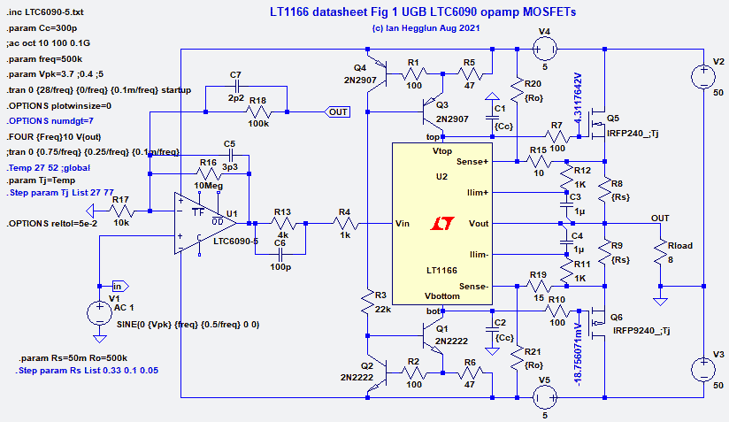
My earlier post 20 using the LT1166 and the LT6090 opamp seems to give sub-ppm distortion at 1W and 1kHz. That's without DoubleCross.
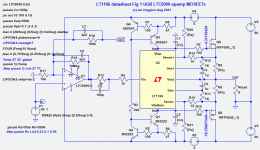
BTW if anyone wants to make Post 20 circuit, the CCS transistors Q1,Q3 will need up rating for Vce. Else use a +/-15V bootstrapped supply for the CCS's then you can use the fast LV transistors. Add an input filter (50kHz 1 pole) and a Zobel (eg 100nF and 2x22R/2W non-inductive).
Hi peufeu,...Besides, an idea I want to try is automatic bias setting: if an amplifier is powered several hours per day, but it is not playing music all the time, then over the years, cost of electricity for a high bias setting becomes significant, perhaps higher than the cost of parts for the amplifier. So, a circuit that automatically reduces bias to a very low level when there is no music would allow a much higher bias when actually playing music, for the same electricity cost. And it gives warms and fuzzies for saving the planet. So that would mean not one bias pot, but two or three, depending on setting: idle/youtube videos/audiophile, etc
An autobias circuit would be ideal for this, because it eliminates the thermal lag at power-up. But putting the sensor on the collector/drain pin makes the bias settle in a few seconds, so it's equivalent....
I think your idea of of 2 or 3 user selectable bias levels has merit - at least to appease the planet saver police. We have noise police so why not power dissipation police😀?
The 3 levels could be user selectable as well as under micro supervision. The micro could determine which setting is appropriate for the music being played based the HF content (ie MP3 or HQ audio) and/or noise floor (S/N). Default bias would be low bias and when you want best quality you reset it higher just before playing your HQ music.
An idea for auto detection of HQ music is to add a 1 cycle burst of 20kHz (CD audio, or whatever the top frequency is for your system) to your recordings to make it easy for your amp to detect it (a simple HF peak detector and monostable lasting say 5 mins). An exact 1 cycle burst doesn't occur in music, so it is unique, and most people wont hear it if it gets played. Alternatively, this first 1cy burst could be blocked using a relay as part of the micro monitor system for bias (to avoid annoying your dog or cat). Sounds like a crazy idea - but lots of DIY stuff is crazy, so shy not😉?
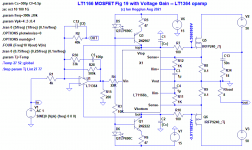
...The next question: Does that safe operation with SR limiting also apply to driving the top and bottom pins with an opamp? Yet to confirm.
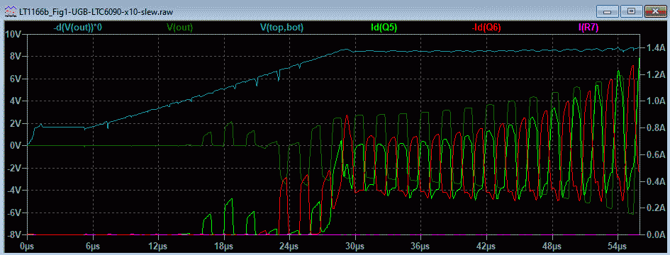
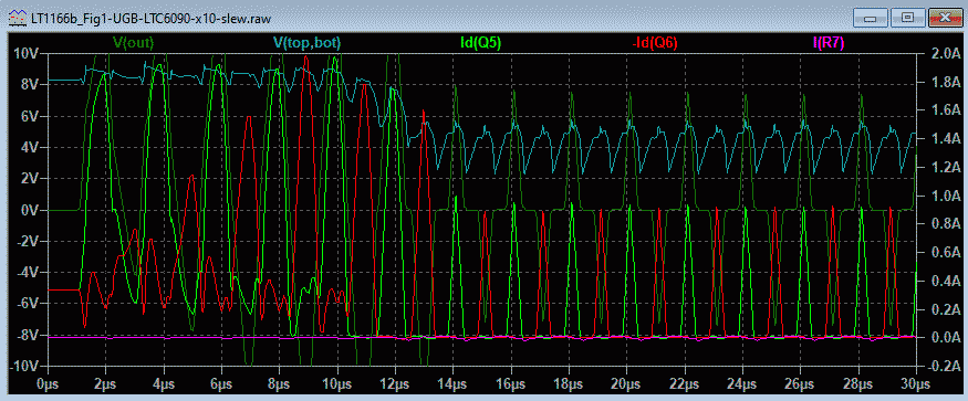
I think the answer is No. Driving the LT1166 Top/Bottom pins with an opamp like the LT1364 at high enough frequency eventually causes cross-conduction that's fatal. Aparently an opamp driving the LT1166 Top/Bottom pins can override the LT1166 bias control function at HF and cause serious problems unless the frequency is limitied.
I used the circuit below
.
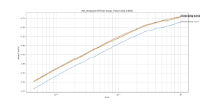
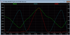
Up to 300kHz at full output just below clip of 40V cross-conduction is starting with the p-MOSFET Id6 at 300mA. With 500kHz both are conducting at crossover at 400mA, and 1A at 1MHz.
.
In Post 9 with drive to the Vin pin cross-conduction did not happen at high frequencies, at 1MHz the bias voltage collapsed and the amp shuts down with no cross-conduction.
So an opamp driving the Top/Bottom pins the LT1166 there is a problem at 300kHz and above which means an input filter should be used. A simple RC filter at 200kHz -3dB did prevent cross conduction up to 1MHz, but 1A cross-conduction was back at 1.5MHz. Looks like a 2nd-order filter is needed (at say 200kHz).
This amp topology allows full output to 200kHz with a slew rate of 40V/us. THD at 40Vpk and 1kHz is 0.002% and idle current is 180mA.
CF Post 20 topology with the LT6060 opamp was 50kHz full power BW and 10V/us slew rate.
Attachments
Besides, an idea I want to try is automatic bias setting: if an amplifier is powered several hours per day, but it is not playing music all the time, then over the years, cost of electricity for a high bias setting becomes significant, perhaps higher than the cost of parts for the amplifier. So, a circuit that automatically reduces bias to a very low level when there is no music would allow a much higher bias when actually playing music, for the same electricity cost. And it gives warms and fuzzies for saving the planet. So that would mean not one bias pot, but two or three, depending on setting: idle/youtube videos/audiophile, etc.
Just switch it off when you are not using it, that's much simpler and far more efficient.
total failure
I'm sorry to hear that the project failed so miserably. Care to share the circuit diagram with all details, so that we can learn from it?
Cheers, E.
Hi Ovidiu,I've tried it years ago (including a slew limitation circuit, I still have some PCBs) and it was a pretty frustrating and expensive total failure. It was impossible to stabilize this autobias circuit under practical conditions (overloading, step response, etc...). The circuit presented appears as a good idea, a great simulation exercise, but otherwise it is useless from any practical perspective. A good lesson to learn for those that believe in designing by simulation only.
I'm sorry to hear that the project failed so miserably. Care to share the circuit diagram with all details, so that we can learn from it?
Cheers, E.
Hi Ovidiu,
I'm sorry to hear that the project failed so miserably. Care to share the circuit diagram with all details, so that we can learn from it?
Cheers, E.
Good luck with that one. 😛
BTW Edmond I'm planning to email you a MC file of my MMXX amp, I'm injecting error current into the OPS and at the same time use the current to make a dynamic bias controll of the OPS.
The OPS is biased at about 26mv across the RE's with the standing current.
Stein
Attachments
MMXX amp
Hi Stein

Cheers, E.
Hi Stein
I still don't know which one failed.Good luck with that one. 😛
You make me curious. Please, tel us more about it.BTW Edmond I'm planning to email you a MC file of my MMXX amp, I'm injecting error current into the OPS and at the same time use the current to make a dynamic bias controll of the OPS.
The OPS is biased at about 26mv across the RE's with the standing current.
Stein
Cheers, E.
Hi Stein
I still don't know which one failed.
You make me curious. Please, tel us more about it.
Cheers, E.
Edmond
I actually have no idea why your best friend Ovidiu don't aswer your question.😉
Btw. without reason he and his good friend called me a Troll in another thread, I will never forget that.
Yes I will tell you more about the MMXX amplifier, but please remember that this a hobby for me and I have limited time.
I will make a document that explains how it works.
All the best.
Stein
EdmondBtw. without reason he and his good friend called me a Troll in another thread, I will never forget that.
1. I have no good friends here, and I don’t feel like making any. My friends belong to another parallel universe.
2. With rare exceptions, I don’t call people “troll”, not even those who deserve it.
3. Please quote where I called you a “troll” or I might believe you are one. I have responded to your posts exactly 11 times since Anno Domini 2009.
4. Why I don’t answer certain questions, i would think it’s none of your business; I could only quote myself from the past “nobody owes you anything here, not even an answer”.
3. Please quote where I called you a “troll” or I might believe you are one. I have responded to your posts exactly 11 times since Anno Domini 2009.
”.
A lot of the posts has dissapeared but here is one that survived.
Its by you and Scott.
And that tongue in cheek comment was about you?
Here's the complete list (in reverse chronological order) of DIYAudio members I ever called "troll" since 2009
petr_2009
KBK
hellokitty123
Here's the complete list (in reverse chronological order) of DIYAudio members I ever called "troll" since 2009
petr_2009
KBK
hellokitty123
Running the LT-XVII LT1166 model
For a comparison I use the LT1166 model (in Special Function library of LT-XVII). The circuit I use below with no Schottky diode or series inductor.
The LTspice LT1166 model shows with yellow in-fill, my custom model in earlier posts has no fill since it is a custom Block type subcircuit. BTW you can open my subcircuit and see the LT1166 circuit (but not with the LT-XVII model).
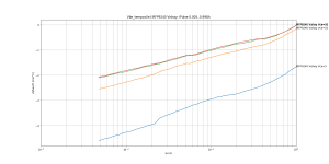
First the LT1166 model with 500kHz below
.
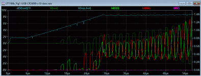
Startup with DC sources from 0V is used because this LT-XVII model did not start with the standard .trans command. I left in running for 2 hours and it still didn't find the operating point. With Startup the circuit reaches steady state after 20us. There is no collapsing of the Top/Bottom voltage like with my LT1166 custom model. But what does a real LT1166 do at 500kHz? I don't have the parts on hand to find out.
Next I uses Startup on my LT1166 custom model at 500khz, below
.
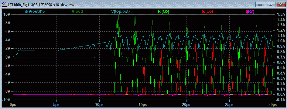
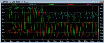
My custom model gives a different Startup showing high cross-conduction (0.8A) and a slow move to steady-state condition (it rans so slow that I used .Options reltol=5e-2 otherwise it would take hours to get to 50us.
Then my custom model without Startup (standard .trans with the DC operating point) below
.
This shows the same collapsing of the Top/Bottom voltage that I reported earlier (Post 9). The reason for the collapsing Top/Bottom voltage is a capacitor in my model which I found made it possible to run the LT-XVII LT1166 model without having to use the Startup flag. That is the main difference of my model, a capacitor on the +bias rail for all the CCS's in the LT1166. Somehow adding a capacitor there allows the DC operating point to be carried over into the .trans run. But as we can see from the above plots this capacitor does not give the same Startup plots as the LT-XVII model. So it a case of pick your poison - there is no trouble free LT1166 model as yet.
BTW LTspice has had 4 versions of the LT1166 - the last one (shipped with LT-XVII) works for most of my circuits-- but in this case it can't find the DC operating point, so I have to use 'Startup'. That's not a big problem, but it can't do .AC runs for this particular circuit because it can't find the DC operating point😱.
What does it mean? My previous conclusion that driving the Vin pin is better than driving the Top/Bottom pins assumes my model is giving realistic results. But I can't be sure my model (and conclusion) is valid until my circuits have been checked with a real LT1166. That will take time... Anyone feel free to do some tests? Like Post 9.
The plot I showed in Post 9 at 500kHz with the Top/Bottom voltage collapsing used a custom LT1166 model....Now with the inductor at 500kHz the LT1166 cannot maintain its proper control and the bias voltage falls causing severe crossover distortion...
For a comparison I use the LT1166 model (in Special Function library of LT-XVII). The circuit I use below with no Schottky diode or series inductor.
The LTspice LT1166 model shows with yellow in-fill, my custom model in earlier posts has no fill since it is a custom Block type subcircuit. BTW you can open my subcircuit and see the LT1166 circuit (but not with the LT-XVII model).
First the LT1166 model with 500kHz below
.
Startup with DC sources from 0V is used because this LT-XVII model did not start with the standard .trans command. I left in running for 2 hours and it still didn't find the operating point. With Startup the circuit reaches steady state after 20us. There is no collapsing of the Top/Bottom voltage like with my LT1166 custom model. But what does a real LT1166 do at 500kHz? I don't have the parts on hand to find out.
Next I uses Startup on my LT1166 custom model at 500khz, below
.
My custom model gives a different Startup showing high cross-conduction (0.8A) and a slow move to steady-state condition (it rans so slow that I used .Options reltol=5e-2 otherwise it would take hours to get to 50us.
Then my custom model without Startup (standard .trans with the DC operating point) below
.
This shows the same collapsing of the Top/Bottom voltage that I reported earlier (Post 9). The reason for the collapsing Top/Bottom voltage is a capacitor in my model which I found made it possible to run the LT-XVII LT1166 model without having to use the Startup flag. That is the main difference of my model, a capacitor on the +bias rail for all the CCS's in the LT1166. Somehow adding a capacitor there allows the DC operating point to be carried over into the .trans run. But as we can see from the above plots this capacitor does not give the same Startup plots as the LT-XVII model. So it a case of pick your poison - there is no trouble free LT1166 model as yet.
BTW LTspice has had 4 versions of the LT1166 - the last one (shipped with LT-XVII) works for most of my circuits-- but in this case it can't find the DC operating point, so I have to use 'Startup'. That's not a big problem, but it can't do .AC runs for this particular circuit because it can't find the DC operating point😱.
What does it mean? My previous conclusion that driving the Vin pin is better than driving the Top/Bottom pins assumes my model is giving realistic results. But I can't be sure my model (and conclusion) is valid until my circuits have been checked with a real LT1166. That will take time... Anyone feel free to do some tests? Like Post 9.
Attachments
-
 LT1166-Fig1-UGB-LTC6090-x10-500kHz-cct.png18.4 KB · Views: 1,570
 -
 LT1166-Fig1-UGB-LTC6090-x10-500kHz-startup.png13 KB · Views: 1,207
 -
 LT1166b_Fig1-UGB-LTC6090-x10-500kHz-startup.png13.6 KB · Views: 1,204
 -
 LT1166b_Fig1-UGB-LTC6090-x10-500kHz.png16.4 KB · Views: 1,223
 -
LT1166-Fig1-UGB-LTC6090-x10-startup.zip9.4 KB · Views: 158
BTW LTspice has had 4 versions of the LT1166 - the last one (shipped with LT-XVII) works for most of my circuits-- but in this case it can't find the DC operating point, so I have to use 'Startup'. That's not a big problem, but it can't do .AC runs for this particular circuit because it can't find the DC operating point😱.
What does it mean? My previous conclusion that driving the Vin pin is better than driving the Top/Bottom pins assumes my model is giving realistic results. But I can't be sure my model (and conclusion) is valid until my circuits have been checked with a real LT1166. That will take time... Anyone feel free to do some tests? Like Post 9.
Ian, excuse my ignorance in LTSpice matters, but in PSpice (which I'm using for the last almost 30 years since I was employed by Cadence) there is the option to save the bias point from a DC analysis and load it for AC or TRAN analysis, isn't this available in LTSpice? Even PSpice 17.4 fails occasionally to converge the bias point.
Secondly, based on my 15 years old results when I experimented with the LT1166, driving the input pin performance was always worse than driving the up/down current sources, in particular at high audio frequencies. I could do something wrong then, sorry, I don't recall the details. I also recall that the big issue was, in practice, the clipping response which was very ugly.
I have no clue what LT1166 models were/are included in LTSpice, here's an unofficial device level LT1166 model I received from a Linear Technology friend and former colleague, way before it was released for the public. This model served me well 15 years ago.
https://www.diyaudio.com/forums/sol...-interview-bjt-vs-mosfet-239.html#post1285491
Hi Ovidiu,
Re: Saving OP. Thanks. I remember keantoken mentioning saving the operating point in LTspice but I have never tried. Looks I need to now that I am out of other options.
Re: Your LT1166 circuit.
Thanks again for that post way back then. I used your circuit and the listing in the link to Bob's interview to create my LTspice model. I also extracted the LTspice model from their library file to check theirs against your listing. The LT-XVII model (4th update) is slightly different to the LT-IV three earlier versions and all are slightly different to your schematic.
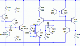
One difference with all LTspice versions and your schematic is both Q20 and Q23 have their B-C reversed! See below.
I compared the two and strangely I didn't find any difference in the external currents. So I used the datasheet circuit connections for Q20 and Q23 in my subcircuit rather than the LTspice models. Maybe one day we will find out if this is a "bug"😱 or a deliberate "feature".
I attach the present LT-IV model as a block subcircuit (revision dated 28 Aug 2018) for anyone wants to look inside and probe inner currents and voltages etc. The BJT parameters can also be easily changed.
The LT-XVII model has a different bias startup arrangement to all earlier versions, but I can't find my block subcircuit just now to show you.
Attachments
- Home
- Amplifiers
- Solid State
- Towards a wideband non switching Auto Bias power amp