Hi,
I'm interested to use a "reset" type switch to fire up my Aleph 5 but don't have the electronic expertise on how to design a small circuit to use this kind of switch.
To make my question a bit clearer: The "reset" type switch only makes contact for as long as it is depressed, therefor I would need to use a relay (I suppose) for the main switch. How do I fire up a power-switch curcuit using a "reset" type switch?
Any ideas?😕
Thanks,😀
Vossie
Most of the large industrial equipment I work on is set up this way. However they use 2 separate buttons one each for on/off. The "On" button needs to be N/O, it ties to the coil on the main power relay. The off button must be N/C and ties between the N/O relay contact and the coil. In this way when you press the "On" switch the relay makes. Releasing the 'On" switch doesn't deenergize the relay as its supplying its own power from its N/O contact.
Hi,
if you want to use two buttons, you can use a relais. Once pressing the on button it holds itself in on-mode. A switch which opens when pressing can be used to disconnect the relais from the power. I suppose you will need an ic like a flip-flop when you want to use a single switch, or am i wrong?
regards,
smithers
I used a finder relay for my aleph 5
only a momentary push button is required.
make a search on "pulse power switch"
or "finder" and you shoud find my previous post.
there is its part number and I believe the price.
If you don't find, ring again and I'll look into it.
only a momentary push button is required.
make a search on "pulse power switch"
or "finder" and you shoud find my previous post.
there is its part number and I believe the price.
If you don't find, ring again and I'll look into it.
From the thread PedroPO is referring to, I ended up buying a Potter & Brumfield (of Tyco Electronics) bistable impulse relay:
Spec sheet:
http://www.pandbrelays.com/datasheets/GP_Power_Relays/S8990_DS.pdf
You can figure out what part number you need at the bottom of the first page of the spec sheet. I ended up going with the 120VAC operated version (for use in the USA) with 20A contacts bought for about $35 from here:
http://www.mouser.com//index.cfm?handler=displayproduct&&lstdispproductid=341943
The design of the relay assembly is pretty straightforward and is amusing to watch for the first few operations. 🙂
For my momentary push button, I used a Vandal switch from Bulgin (www.bulgin.co.uk), the MP0031 for my 1/4" (6.35mm) front panel, purchased for ~$14 from www.newark.com. I picked up the Vandal switch hint from a thread where an Aleph used one obtained from Conrad.
One could also ...
build a low current rectifier for the AC line, zener regulate some voltages, using LARGE resistors, and use power mosfets for switches. Of course, this is troublesome because you need to put 2 mos in series for each switch to prevent the bulk diode from conducting, and (I think) you'd need both PMOS and NMOS...
Has anyone done this with FETs?
just use a flip flop
you need a little "debounce" on the switch (which can be a little RC network) the first push of the switch "sets" the flip flop and the next pulse toggles it to "unset" -- flip flops cost about $0.25. Of course, the f/f should drive the base of a transistor as they won't handle a lot of current.<p> You can also use a "momentary off" or "momentary on" switch.
you need a little "debounce" on the switch (which can be a little RC network) the first push of the switch "sets" the flip flop and the next pulse toggles it to "unset" -- flip flops cost about $0.25. Of course, the f/f should drive the base of a transistor as they won't handle a lot of current.<p> You can also use a "momentary off" or "momentary on" switch.
I to want to control my amps with a low power easily pushable momentary contact switch.
My AX amps will have a power supply in a separate case to keep the amps cooler. Each amp will have a button on it that turns all the amps on with one push and then turns all the amps off with another push. I have really no electronic expertise, but even I can figure out how a relay works. So after using up a lot of scrap paper I finally figured out how to do it😀 . My circuit uses two latching relays in a type of flip – flop. The relays go throw 4 cycles, two turn the amp on and two to turn the amp off. All that clicking inside should sound really neat. I don’t like using semiconductors, the relays will last longer. I have not tested this idea, but I believe it will work, because there is very little that could go wrong. I have not filled in any of the values, even people without electronic expertise should be able to figure out with they are. If anybody builds this please let me know how it works.
Levente B. Hajdu
LBHajdu@optonline.net
Attachments
Beware of inrush currents!
If you power up all your transformers simultaneously you'll most likely take out the trip on your fuseboard.
You need a power sequencer to wait a few seconds bedtween powering up each transformer, don't know if anyone has a suitable circuit.
Perhaps you could use some readymade 555 timer PCB's with different delay times on them to fire your relays?
Jason,
Actually I’m using Nelsons method of using a thermistor on one of the ac lines. That’s what the resistor you see there is. This method is cheaper and less likely to go bad over time then a whole complex setup with a 555 timer. Question, so why don’t more amps use it. Answer, because not all amps draw a constant current and the thermistor needs a constant current to heat up so its resistance can drop. This method should not be used for example with a class d amp.
Leve
Hi!
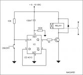
I use this circuit in all my equipment. It works very well. You need a small standby transformer (1-2W), rectifier and filtering.4013 is a dual D Flip Flop, so you can use the other flip flop for a mute circuit or something similar. I didn't have any problems with contact bounceing, but you can use a little RC filter (10nF+1K) across the switch contacts. I hope this helps.
I use this circuit in all my equipment. It works very well. You need a small standby transformer (1-2W), rectifier and filtering.4013 is a dual D Flip Flop, so you can use the other flip flop for a mute circuit or something similar. I didn't have any problems with contact bounceing, but you can use a little RC filter (10nF+1K) across the switch contacts. I hope this helps.
Attachments
Relay closing at low ac voltage
Feature-wise, I would like to see the AC switching relay closing at low AC voltage, ie: when the line voltage cross the zero. This is to avoid arcing across the relay contacts. I have a Motif MS-100 that arc so often that the contacts eventually welded together.
Perhaps we need to use solid state relay for faster switching ?
Anyone ?
More...
After searching a bit more in the net I found a lot of circuits with relays but you need a secondary power source to operate the relay - I don't want any extra interference.
Can't you use a bit of the mains to momentarily close the relay and then use some current from the "switched on" circuit to keep the relay closed.
...over the one of you more educated folk...
Vossie😎
arcing across relay
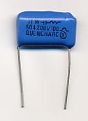
Mallory (the capacitor company, not the mountain climber) has a good tutorial on what can be done to reduce arcing in relay contacts (bad as it oxidizes the contacts, increasing resistance, or worse still, just blows the contactor apart.)
Basically relay contacts can be viewed as the plates of a capacitor. When they get closer current will begin to flow before they make contact. If you put a capacitor and resistor (snubber) in parallel with the relay contacts its value swamps the value of the capacitance of the relay contacts. A snubber should not effect sound quality since it is shorted out by the relay making contact.
Vossie, I have used a 1 Farad/6 volt cap to turn on the relay. Once the circuit is on, I used the main power supply to charge the cap and power the relay. Bil
Member
Joined 2002
nagard said:Hi!
I use this circuit in all my equipment. It works very well. You need a small standby transformer (1-2W), rectifier and filtering.4013 is a dual D Flip Flop, so you can use the other flip flop for a mute circuit or something similar. I didn't have any problems with contact bounceing, but you can use a little RC filter (10nF+1K) across the switch contacts. I hope this helps.
What is the chip that is used. ? any one know the part number ?
i want to start a few of these.
Member
Joined 2002
- Status
- Not open for further replies.
- Home
- Amplifiers
- Pass Labs
- touch button power switch circuit