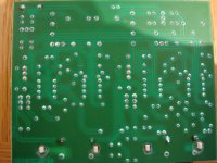
post a high quality pic of the trace side of the PCB, particularly the top half that includes the PSU and connections to the amplifiers.
To answer Mooly's questions surrounding voltage...
Grounding on the RCA outputs I get the following voltages:
A: 0v
B: 23.3v
C: 0v
D: 14.3v
My multimeter does also have a diode function where I get the following readings...
The burnt one I get zilch
The one next to it I get .631 as a reading
The one that is top left of the board in the picture I get 1.205
I don't know what measurement these readings are in and have no idea if they have any bearing.
I bought the diodes yesterday but they had two types in stock, Silicon and Germainium?
Both had the same characteristics with regard operation so I bought both types.
A whole 96p later I had them in my pocket!
So, what's next?
Cheers all.
I would just change the two diodes. Only one has failed but in a doubler it does help to keep everything similar.
This is about as good as I can get with this camera and setup.
Hope this is sufficient. I think you can see the trace all round the PCB now.
Shall I crack on and replace that diode? See what happens? Can't get any worse than now as it currently doesn't work at all and this is the last resort before buying another one.
Cheers
Hope this is sufficient. I think you can see the trace all round the PCB now.
Shall I crack on and replace that diode? See what happens? Can't get any worse than now as it currently doesn't work at all and this is the last resort before buying another one.
Cheers
Attachments
In relation to Andy5112405 - What should I do about this diode that is showing as having double the voltage across it than the burnt out one?
Also, if adding a 16v DC voltage can't cause this damage, what else might have caused it?
Cheers
Also, if adding a 16v DC voltage can't cause this damage, what else might have caused it?
Cheers
Replace the burnt diode with any of the new ones. The "stripy" end goes toward the other diode I.E that is to say the stripe goes to the orange wire.
The G in the part type often stands for "glass passivated"... it makes zero difference here any will be fine.
There is a remote possibilty there is a further problem... I think in the first instance you have to just power it up and very quickly measure and see if the voltage on the replaced diode comes up. If it doesn't then the diode is probably getting hot and we need to investigate further. In fact the best initial test may be just to power up with your finger on the diode and make sure it is cool.
In relation to Andy5112405 - What should I do about this diode that is showing as having double the voltage across it than the burnt out one?
Also, if adding a 16v DC voltage can't cause this damage, what else might have caused it?
Cheers
Worry about all that if it doesn't work... reading parts in circuit gives "false" readings... a good chance it will all work 🙂
I was just going to say what Mooly has just posted. If you want true readings from the diodes then lift one end of them. Theyshould ALL read about 0.7V unless one is a zener.
0.6 - 0.8V is fairly common.
0.6 - 0.8V is fairly common.
An externally hosted image should be here but it was not working when we last tested it.
I hope this is clear. This is how the Black 1N400x's should be inserted.
Andy
Righty ho all,
Soldered in the new diode's (the two at the top that are in series) but I haven't done the one over on the left.
It's still not working.
I've tested the voltages across the diodes and the two new 1N4002's that I put in now read equal (nearly) but the one on the left reads 0.605 if I read it one way, but 1.2v if I reverse the polarity.
The new ones don't do this. Does this mean this doiode is also a bit had it?
Also, is the blue component below the diode over on the left also a diode? I tested it just in case and it reads .205 in one direction and 1.2 with the polarity reversed. The same as the diode above it.
Any help is as always, appreciated!!
I'm going near maplins again tomorrow so any help this evening is great!!
Thanks all.
What are the two voltages A and B as per the previous picture. Is voltage A still low ?
Before you do that put your meter on "low" ohms range and with preamp off measure from ground (phono sockets) to point A. What does it read ?
Before you do that put your meter on "low" ohms range and with preamp off measure from ground (phono sockets) to point A. What does it read ?
A=24.2v
B=23.7v
I'm sorry but what does "low ohms" mean? I can upload a picture of my multimeter if necessary! Electrical engineer I most certainly am not! Lol!
B=23.7v
I'm sorry but what does "low ohms" mean? I can upload a picture of my multimeter if necessary! Electrical engineer I most certainly am not! Lol!
Those voltages sound OK apart from the fact that A should be a negative voltage 🙂
I'll look in again in half an hour...
What is the voltage on points C and D ?
Is there any sign of anything getting hot ? The regulators ?
Low ohms means a range that would measure a resistor such as 10 ohm and give an accurate reading.
I'll look in again in half an hour...
What is the voltage on points C and D ?
Is there any sign of anything getting hot ? The regulators ?
Low ohms means a range that would measure a resistor such as 10 ohm and give an accurate reading.
Right! Good spot! The -ve is a -ve ad it should be!
Don't think my multimeter can do the"low ohms" reading. However...
C=0.70v
The one above C=12.35v
D=14.8v
Cheers all!
Don't think my multimeter can do the"low ohms" reading. However...
C=0.70v
The one above C=12.35v
D=14.8v
Cheers all!
Is the regulator getting hot ?
We need to narrow this down... are you quick at unsoldering ? Are you using solder braid ?
1. Remove the white diode in the top left of your very first picture. Switch on and see if voltage C appears. That's pin 4 of the IC and it should be -15v
We need to narrow this down... are you quick at unsoldering ? Are you using solder braid ?
1. Remove the white diode in the top left of your very first picture. Switch on and see if voltage C appears. That's pin 4 of the IC and it should be -15v
As a quick aside my 16v ac adaptor is putting out 17.9v ac.
Could this cause an issue?
That's normal... it's just a transformer and the voltage depends on current drawn and how low or high the mains is... no problem there.
Nothing appears to be getting hot. Been left plugged in for a while now. All seems stable.
I can unsolder that diode but it's a bit iffy as this board is biased towards dry joints. Hmmm. Could that be an issue?
Also, no idea what solder braid is, but I'm pretty sure my solder is pre-fluxed. It's damned old though. Like 20 years+! lol!
I can unsolder that diode but it's a bit iffy as this board is biased towards dry joints. Hmmm. Could that be an issue?
Also, no idea what solder braid is, but I'm pretty sure my solder is pre-fluxed. It's damned old though. Like 20 years+! lol!
OK let's slow down and be logical. It's an easy fix as this is a simple circuit, it's just a case of finding the problem by logical steps.
The negative 24 volts or so is now correct.
That feeds into the regulator. There are 3 pins on the reg. One is the input, one the output and the other ground.
It's possible there could be a short on the negative rail so we have to isolate things to see where the problem is.
Just unsolder one end of that white diode. It's done in a second... heat and pull 🙂
Or you can just snip the lead such as it can be resoldered. We can always fit new later.
- Status
- Not open for further replies.
- Home
- Source & Line
- Analogue Source
- Total noob with blown Pre-amp