Hi all,
I really am a complete noob to the site but I need help.
I'm fairly good with a soldering iron but knowing what to solder is currently beyond me!
I have a Pro-ject Debut II turntable running through a Pro-ject Phono Stage. It was packed away for a while during some renovations to the house and when I unpacked it I managed to plug the incorrect transformer into it. I plugged a 16v DC transformer in rather than the correct 16v AC transformer, resulting in a puff of smoke and no sound. I've opened up the casing of the phono stage and found what appears to be a blown resistor on the AC input.
I've tried to read through the thread about the Pro-ject phono stages but I'm afraid it is way beyond my knowledge levels.
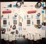
I have included a photo of the circuit board, could someone tell me what value the resistor is that is blown. It's not hugely apparent as the flash from the camera bleached out the burn mark so I have circled it in red.
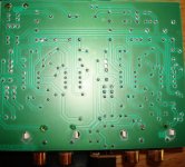
I have also included a photo of the circuit side of the board. Sorry that it is reversed but my brain isn't working too well and I can't get photoshop to reverse it.
If you could also suggest if anything else may have been damaged in the incident 🙂
Cheers all
I really am a complete noob to the site but I need help.
I'm fairly good with a soldering iron but knowing what to solder is currently beyond me!
I have a Pro-ject Debut II turntable running through a Pro-ject Phono Stage. It was packed away for a while during some renovations to the house and when I unpacked it I managed to plug the incorrect transformer into it. I plugged a 16v DC transformer in rather than the correct 16v AC transformer, resulting in a puff of smoke and no sound. I've opened up the casing of the phono stage and found what appears to be a blown resistor on the AC input.
I've tried to read through the thread about the Pro-ject phono stages but I'm afraid it is way beyond my knowledge levels.
I have included a photo of the circuit board, could someone tell me what value the resistor is that is blown. It's not hugely apparent as the flash from the camera bleached out the burn mark so I have circled it in red.
I have also included a photo of the circuit side of the board. Sorry that it is reversed but my brain isn't working too well and I can't get photoshop to reverse it.
If you could also suggest if anything else may have been damaged in the incident 🙂
Cheers all
Attachments
Hi,
plugging in a DC voltage to a PSU expecting to be fed with an equal value AC voltage will not do any harm.
Something else happened.
Can you get a magnifying glass and examine the resistor to identify some or all of the colours?
Most of the circuit is two channels with identical component placement.
The bits that are different are at the input and the output.
At the input I cannot see any diodes. I suspect this circuit expected a DC supply and you plugged in an AC supply to kill it.
Last edited:
Colday: it is a diode that you marked. This thing appears to use two regulated rails derived from one AC voltage, and the two diodes in the upper (on the photo) part of the PCB are the rectifiers, one of them you say is blown. The regulators normally accept up to 35 volts, so 16v DC would not hurt them anyway. I wonder what might create smoke there... Try to plug in the normal AC adapter and measure voltages across the two bigger electrolytic caps in the upper part of the board. They should be identical, plus and minus 20V or so, maybe less. If one voltage is missing, you did blow a diode, replace it. If both are present, measure the voltages at the outputs of the regulators - those three-terminal TO-92 in the upper part surrounded by blue ceramic caps. Should be (I guess) plus and minus 15V.
AndrewT: Pro-ject Phono Box does require 16V 30mA AC (not DC).
AndrewT: Pro-ject Phono Box does require 16V 30mA AC (not DC).
Last edited:
Looking quickly at the PCB layout, the two DIODES form a classic voltage doubler to produce + and - supplies from a single AC source.
This would not work if you attach a DC supply.
The circled component is a DIODE. I would simply replace the two diodes at the top centre of the board with 1N4002s and see if it works.
This would not work if you attach a DC supply.
The circled component is a DIODE. I would simply replace the two diodes at the top centre of the board with 1N4002s and see if it works.
Its a diode to replace its my guess too from as much as I can make out. Are those TO-92s something like 78L15 regs? Not likely to have been hit though.
I either need a bigger and higher resolution monitor or I need newer prescription spectacles.
Ignore what I said.
Ignore what I said.
Thankyou all!
Including AndrewT, it sounded good anyhow! ;-)
So, if I go into Maplins and ask for some 1N4002s Diodes they will know what I mean?
Also, when I said I was a noob, I really meant it. Could someone translate Salas' line for me as I really have no idea!
"Are those TO-92s something like 78L15 regs? Not likely to have been hit though. "
Cheers all.
The three legged black blobs at the top of the circuit board are most likely voltage regulators.
They will take the high voltage from the diodes and associated capacitors and turn it into + and - voltages suitable for the remainder of the circuit.
Looking into the circuit, there is no reason why the diode should have failed. Connecting DC across the doubler in either polarity would not cause the diode to fail unless one of the electrolytics is short circuit. (The large black capacitors).
Maplins stock of components is becoming limited. 1N4002 / 1N4003 / 1N4004 will all work, the increasing number is just increasing voltage handling, so even 1N4007s will do the job.
Burn mark ? or just heat discolouration which may be normal.
Yes 1N4002 diodes are common. 1N4001/2/4/7 are all the same series... any would do, higher number, higher working voltage but any OK here.
Can you couple it up to the tranny and do a couple of quick voltage checks first before condeming things...
Can you measure from "ground" (phono socket outers) to each end of the two diodes on a DC voltage range on your meter.
I will have to do all the measurements tonight when I get in, I'll buy a couple of the diodes as Maplins is miles from us and we are visiting relatives.
Cheers all again!
Cheers all again!
Do you have a DIODE function on your multimeter ?
If you are trying to measure the resistance of diodes you will get some odd results.
Mooly is assuming that the diodes are possibly OK. I agree with him, there is no reason that one should have failed.
If you are trying to measure the resistance of diodes you will get some odd results.
Mooly is assuming that the diodes are possibly OK. I agree with him, there is no reason that one should have failed.
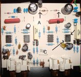
If voltage A and B are around plus and minus 20 volts then the diodes are OK. Voltage A will be the negative one and B the positive reading.
What you do next depends on that outcome. If Maplin is miles away then try and get replacements for the two regulators whatever they are at the same time.
There are two diodes at the opposite corner to where the AC comes in. One looks like a zener and the other a normal diode. Bit hard to visualise but they may be to do with ensuring correct startup under "race" conditions whereby the regs latch in an unpredictable state. For what they cost... worth getting new just in case.
To answer Mooly's questions surrounding voltage...
Grounding on the RCA outputs I get the following voltages:
A: 0v
B: 23.3v
C: 0v
D: 14.3v
My multimeter does also have a diode function where I get the following readings...
The burnt one I get zilch
The one next to it I get .631 as a reading
The one that is top left of the board in the picture I get 1.205
I don't know what measurement these readings are in and have no idea if they have any bearing.
I bought the diodes yesterday but they had two types in stock, Silicon and Germainium?
Both had the same characteristics with regard operation so I bought both types.
A whole 96p later I had them in my pocket!
So, what's next?
Cheers all.
In addition to Salas' comment earlier in the thread, on looking closley the TO-92's (don't understand this bit) have different readings on them.
Looking at the component picture the TO-92 to the right is a 78L15 while the one on the left is a 79L15.
No idea if this makes a difference but I have had a couple of people have a look and we all agree that's what is printed on the component.
Cheers
Looking at the component picture the TO-92 to the right is a 78L15 while the one on the left is a 79L15.
No idea if this makes a difference but I have had a couple of people have a look and we all agree that's what is printed on the component.
Cheers
the diode function is showing the voltage across the diode while the meter is passing a DC current through the diode.
This is nearly Vf in the datasheet except that the wrong temperature and the wrong current are being used.
0.631V is a plausible Vf'
1.2V cannot be right.
Zilch cannot be right.
The To92 voltage regulators come in two versions 78 is the +ve type and 79 is the -ve type.
79L15 tells you it is a -ve regulator, L tells you it is the low power version, 15 tells you the output voltage. So you have -15V voltage regulator that can pass <=100mA
Download the datasheets for 7815 and 7915 and 1n4002 to see all the information about these silicon based semiconductors.
Looks like the diode is blown so you'll have to replace it, and make sure the replacement goes in the right way around, or there will be worse damage.
It's a bit worrying that they offered silicon and germanium. It needs to be silicon, not germanium, but you also need the right type of diode. It should be a power diode like 1N4004 (biggish black plastic body). If you put in a small signal diode like 1N4148 (tiny glass body), it will probably go pop straightaway.
It's a bit worrying that they offered silicon and germanium. It needs to be silicon, not germanium, but you also need the right type of diode. It should be a power diode like 1N4004 (biggish black plastic body). If you put in a small signal diode like 1N4148 (tiny glass body), it will probably go pop straightaway.
I bought 1N4002 Diode's
2x1N4002S and 2x 1N4002G
Silicon and Germanium (He mentioned glass aswell for the G)
Looking at their datasheet the only difference appeared to be that the wire going into the component was 0.1mm thicker with the silicon ones.
Cheers
2x1N4002S and 2x 1N4002G
Silicon and Germanium (He mentioned glass aswell for the G)
Looking at their datasheet the only difference appeared to be that the wire going into the component was 0.1mm thicker with the silicon ones.
Cheers
I suspect the "G" suffix may be a "rohs" code and nothing to do with germanium.
The 1n400x is a silicon based device.
Can you disconnect the PSU at the top of the PCB from the amplifier in the middle of the PCB?
This will allow you to "test" and measure the PSU output voltages before you damage the rest of the circuit.
The 1n400x is a silicon based device.
Can you disconnect the PSU at the top of the PCB from the amplifier in the middle of the PCB?
This will allow you to "test" and measure the PSU output voltages before you damage the rest of the circuit.
- Status
- Not open for further replies.
- Home
- Source & Line
- Analogue Source
- Total noob with blown Pre-amp