I'm not so sure there are any tants in there. That looks more like a monolithic filter (coil etc) of some sort encapsulated in epoxy.
I didn't see any tantalum on the board. However I was curious of what these clear things with capacitance markings were. The only thing I saw similar online were some pictures of similar ones that were supposedly glass...
"Use new organic membrane as the medium; The aluminium foil is the electrode; There are sensing types that are coiled; Envelopment of transparent resin; Copper plated CP outgoing line. The wide, insulation resistance of range of capacity is large, good electrical performance.
Suitable for generally filtering, the signal couples and low pulse circuit."
With that said. I'm leaving them alone until I get my capacitance meter on them and see IF there is a replacement for anything like this. Most likely I'm just going to leave them alone regardless of what they test out. (Unless shorted of ourse)
They are plain old polystrenes, very common and sometimes might be referred to as 'Suflex' types.
Leave them be 😀 Tuner remember... even moving them could alter the alignment of the RF stages as you change the stray capacitance and inductance as they relate to other nearby parts.
Leave them be 😀 Tuner remember... even moving them could alter the alignment of the RF stages as you change the stray capacitance and inductance as they relate to other nearby parts.
Thanks Mooly! This has been a fun learning experience!
Btw the tuner worked flawlessly before I started recapping
Btw the tuner worked flawlessly before I started recapping
You are welcome 🙂
and I hope it still does after the recapping too. Electrolytics you are fine to change, but anything else in the tuner section... well, don't even think about it.
Btw the tuner worked flawlessly before I started recapping
and I hope it still does after the recapping too. Electrolytics you are fine to change, but anything else in the tuner section... well, don't even think about it.
Polystyrene. Don't touch, they are sensitive to heat (your soldering iron), but are otherwise not failure prone. The orange round blobs behind them on your pic there are tantalum. Those are the only caps in there that actually need replacing.
Do you mean the little yellow ones?
well that was entertaining... lights up and looks pretty, no output, no tuning, around 1v out the speaker terminals
i wish someone had a freakin service manual for this thing
i wish someone had a freakin service manual for this thing
so at this point im not sure what to do other than start putting the old junk green caps back in and set the new ones aside
all the electrolytics have been changed with same value nichicons
and before i knew to leave the tuner alone, all the little green plastic film caps were replaced with nichicon qyx series
all the electrolytics have been changed with same value nichicons
and before i knew to leave the tuner alone, all the little green plastic film caps were replaced with nichicon qyx series
Attachments

Last edited:
im just hoping its something stupid like a jumper that got loose.... very frustrating at this point, i was hoping for a grand finale with great sound and functionality before i went on to the cosmetics
You mean you've broken it 😱
The diagram you posted at the start is all you need. A full manual wont tell you any more beyond alignment procedures.
There is a pre/main switch with jumpers and sockets so if the switch was set incorrectly/and/or jumpers missing there would be no output. Check that, then check the basics. Begin with the why there is 1 volt acorss the speaker outputs. Check the rails as a first step.
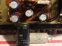
Ripple current rating is (one) of the important factors when choosing replacement caps for a PSU. Modern caps are much smaller than those of yesteryear but it pays to be sure.
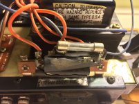
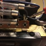
A soldered fuse is infinitely preferable to a holder... if you worked in a service dept you would be amazed at the number of faults/intermittent faults directly attributable to holders that had weakened and were causing an intermittent or high resistance connection.
A soldered fuse is infinitely preferable to a holder... if you worked in a service dept you would be amazed at the number of faults/intermittent faults directly attributable to holders that had weakened and were causing an intermittent or high resistance connection.
Ok so I'll get new fuses and probably run new wire to the solder tabs. As far as ripple current, I can tell you exactly what the new ones are but have no clue what the old ones were. Every cap I used was nichicon low esr type
If that stereo is less than 100 watts, I doubt the designer even looked at the ripple current ratings on the caps. Because in practice at normal listening levels it just isn't that high. And the new caps are likley better anyway.
I was also able to locate someone online who reproduces the service manuals!
Parts list, test points, adjustments, actual specs. Neat stuff!
According to this document. The original specs are.
0.8% distortion at rated power output
RMS power;
22w 4ohm
30w 8ohm
18w 16ohm
Parts list, test points, adjustments, actual specs. Neat stuff!
According to this document. The original specs are.
0.8% distortion at rated power output
RMS power;
22w 4ohm
30w 8ohm
18w 16ohm
- Status
- Not open for further replies.
- Home
- Amplifiers
- Solid State
- Toshiba sa-400