Guys, I know you will throw sticks and stones at me after this...but...ermm....cough...I would stay away from transformers with built in thermal fuses that when they blow you have couple of kilograms of wasted copper and expensive waste as well. I prefer those with nothing or built in NTCs. With a simple circuit and a relay you can make your transformer safe from overheating and avoid destroying the sucker.
Sorry but both fuses are in series, so 0.5A fast blow is the one who works ... and it will blow on turn-on, even if PT is unloaded, just from magnetizing current.Slow blow fuse on the hot lead for the transformer primary, guessing a 1.25A rating given the 80VA transformer. Fast blow for the return leg on the primary, guessing a 0.5A.
Sorry but too tight, it will nuisance blow often, if not all the time.Probably 400 mA T for 80 VA at 230 V,
Try at least 50% higher.

why are you sorry. If I got it wrong, I got it wrong. I'm used to US wiring. Thanks for the correction.
Sorry but too tight, it will nuisance blow often, if not all the time.
Try at least 50% higher.
You are right, for toriods, such a tight fuse only works when it has a high I2t value. 630 mA T then, or preferably whatever the transformer manufacturer specifies.
An 80VA transformer is only just over 1.5A at +/- 24V. Is that enough?
Measuring 80V across the rectifier output is about right, 24 x 2 x root2 for peak of sine, x 1.1 for mains tolerance x 1.1 or 1.5 for transformer 'regulation' Minus 1.2 for a couple of diodes.
I have one of those mains plug units which measures current, power, kWh used by a device plugged in. One of those might give warning of the primary current getting high.
Fit a couple of 2A or even 1A car fuses in the 24V AC lines. fuses are cheap.
Then test the power supply with something like a few car bulbs in series?
Then check out the 9V converter, does it blow the fuse? What current does it draw?
What is the amp?
The data sheet on the makers web site is a bit different, 50C temp rise fully loaded
https://www.vigortronix.com/wp-cont...-xxxx-2-Series-Dual-Primary-Toroida-D0008.pdf
Most transformer windings fail at somewhat over 100C. You need to add the temperature in the box to the 50C temp rise to get an idea how hot it will get,
The transformer should give it's 25v rms fully loaded. With no load add the regulation %. DC with a full bridge rectifier will be a bit less than the root 2 factor suggests due to diode drops.
I assume you have used the correct type of mounting kit. Lash ups with bits of metal can cause shorting turns,
Thanks for all the replies! Looks like best way forward is to put fuses on the primary side and then gradually build build from there.
Just want to check then, since there seemed to be differences of opinion of fuse size etc.
is it best to use inline fuse holder? Slow blow on the hot from mains to transformer (1.6a), and then fast blow from transformer back to main, (about 0.6a)?
I’ll post more details and pics of my setup when I get the chance…
I’ve got a little lost along the way! So what would you recommend on the hot from mains to transformer, and on return transformer to mains? Thanks again everyone for the help on this 😊🙏Sorry but both fuses are in series, so 0.5A fast blow is the one who works ... and it will blow on turn-on, even if PT is unloaded, just from magnetizing current.
Sorry but too tight, it will nuisance blow often, if not all the time.
Try at least 50% higher.
Send and return to/from mains are in series, that transformer primary is between them does not change that (by the way it's also in series with them) so one fuse protects the whole string.I’ve got a little lost along the way! So what would you recommend on the hot from mains to transformer, and on return transformer to mains? Thanks again everyone for the help on this 😊🙏
Good practice is to fuse Hot lead, so if it blows, the whole transformer becomes cold/safe.
If the return fuse opens it can give you a false sense of security (hey| amp is OFF, now I can work safely with it)
For 150VA transformers and 220/240V mains I use 1.5A slow/T fuses or 2A regular/”fast" ones.
From practical experience they are a good compromise between safety and nuisance blowing.
In general Toroids have lower inductance or DCR than EIs , good for regulation, harsh on fuses.
"Everything" in the Real World is a compromise, we try to find the best one.
Yes you should absolutely get fuses but they would not blow if you put it together correctly.
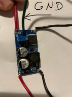
From the pic of the transformer I would have assumed the secondaries 0V would be red and orange and I agree the buck converter looks iffy, how is it connected wrt ground?
From the pic of the transformer I would have assumed the secondaries 0V would be red and orange and I agree the buck converter looks iffy, how is it connected wrt ground?
Thanks for this 😊 If I got a fused IEC switch on the mains side, would that be the place to add the fuse, or should it come after the switch?Send and return to/from mains are in series, that transformer primary is between them does not change that (by the way it's also in series with them) so one fuse protects the whole string.
Good practice is to fuse Hot lead, so if it blows, the whole transformer becomes cold/safe.
If the return fuse opens it can give you a false sense of security (hey| amp is OFF, now I can work safely with it)
For 150VA transformers and 220/240V mains I use 1.5A slow/T fuses or 2A regular/”fast" ones.
From practical experience they are a good compromise between safety and nuisance blowing.
In general Toroids have lower inductance or DCR than EIs , good for regulation, harsh on fuses.
"Everything" in the Real World is a compromise, we try to find the best one.
So here’s the instructions from the seller re hooking up the power board:Yes you should absolutely get fuses but they would not blow if you put it together correctly.
From the pic of the transformer I would have assumed the secondaries 0V would be red and orange and I agree the buck converter looks iffy, how is it connected wrt ground?
CONNECTING THE POWER SUPPLY
Connect the leads from the secondary side of the transformer to the end of the board marked “AC IN”. The two wires from
the transformer centre tap (normally black wire and yellow wire, but please check your transformer datasheet before
connecting) should both be connected to the terminal marked “0V”. The other two (from the transformer outer taps) wires
must be connected to the terminals marked “AC1” and “AC2
And image from transformer data sheet:
I notice that the actual secondaries on the image of the transformer are not the same order as in the diagram, but guessing that’s just the way the diagram is drawn for simplicity.
Yes, good idea!It might be worth people knowing more about the amp you are using. Speaker as well.
Here’s the ebay blurb:
This is v1.4 of the board, with an RCA connector for the input signal as well as a terminal block.
The board was designed in the UK. We also sell this amp as a PCB only. Check out our store.
These amplifiers are truly amazing, capable of delivering up to 68W, with extremely low THD and sporting many advanced features such as under/over voltage & thermal protection etc.
There's provision for a 0.1 ohm resistor for connecting boards in parallel.
Size: W 70mm H 35mm.
To finish this amp you will need:
1x LM3886 amplifier IC.
1x 1uF metallised polyester capacitor.
3x 100uF 50V electrolytic capacitor.
1x 22uF 50V electrolytic capacitor.
3x 22k 1% metal film resistor.
2x 1k 1% metal film resistor.
1x 3-way 5mm terminal block.
1x 2-way 5mm terminal block.
1x PCB mount RCA connector (white or black colour).
You will need to attach a heat sink as the LM3886 is a powerful chip and dissipates a lot of heat.
You will also need a way of powering the amp up. Check our store we have a dual voltage power supply board that is perfect for the job..
I had connected it to ground from the power supply rail to a point I was advised by a question I posted on Amazon. Shown below…. but now I look at it close up I’m wondering if it’s been attached to the positive supply in…Yes you should absolutely get fuses but they would not blow if you put it together correctly.
From the pic of the transformer I would have assumed the secondaries 0V would be red and orange and I agree the buck converter looks iffy, how is it connected wrt ground?
That looks like a short between In- and ground. The buck converter does not have a symmetrical input/output.
Looks like its this one
https://www.ebay.co.uk/itm/124906137289?hash=item1d14fc66c9:g:70YAAOxyVaBSvW7~
I think the power supply board they do would benefit with higher uF caps but that shouldn't be your problem,
From memory the chip gives 60 odd watts with a 4ohm speaker +/- 28v. I'd have though that would be ok with the transformer they suggest. If 2ohm or if it has problems that may cause the transformer to overheat.
That looks like a short between In- and ground. The buck converter does not have a symmetrical input/output.
Attachments
But that IS possible and it is exactly what we did in continental Europe. All transformers in the grid are adjustable, they have to be, and during the change from 220 V to 230 V no "vast amounts of infrastructure" needed to be changed.It is 240V, always has been. Appliances are rated for 230V showing they are compatible with both mains standards. The mains voltage and its frequency are strongly related by the hardware in the system, so you can't just dial down the voltage without replacing vast amounts of infra-structure (and incurring increased system power losses). They now describe UK mains as 230V +10%/-6%, which is 216--253V, which is also 240V +5%/-10%. But nothing has changed physically. You could call it 220V -2%/+15% if you wanted, but its still 240V and not suitable for 220V-only appliances.
Today my local mains is 243.7Vrms...
The amount of PV systems has risen so quickly in the last couple of years that the electrical grid, at times, cannot cope with all the power generated. This means that on sunny days, mains voltage sits at the max allowed 253 V for long periods of time (at the inverter end, depending on the length and thickness of cable used, at the meter end that will be a couple of V lower). Where I live, mains voltage must be within 230 V +/- 10%, meaning 207-253 V (10 min. average, so short excursions beyond these limits are allowed).
So 230/240 V devices are rated at their nominal voltage, but they must be designed to tolerate 253 V indefinitely. It also means they must be designed to function normally at 207 V.
Last edited:
- Home
- Amplifiers
- Solid State
- Toroidal transformers burning up