Hello all 🙂
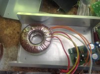
Would any body be able to help me out here, I got this toroidal transformer from Jaycar but am uncertain what wire goes to what.
I've tired to look for a wiring diagram but came up unsecessful 🙁
It is to be connected to this amp: Altronics - K5130 50W Amplifier Module Stereo Kit
The transformer is 25 + 25 160VA toroidal transformer.
Cheers 🙂
Attachments
Usually there is a legend on the side of the transformer. If not, check the resistance of each of the windings. The secondary 25 - 0 - 25 may be Red - Yel - Red as it looks like the wire is a larger guage. Good luck!
Hi Biggie
From your description I'm assuming you have the MT-2114 transformer.
If this is the case, join the Yellow and Pink leads and connect to ground.
The Purple and White leads go to the AC or ~ terminals of the bridge rectifier. The diagram supplied with the kit should make it clear.
From your description I'm assuming you have the MT-2114 transformer.
If this is the case, join the Yellow and Pink leads and connect to ground.
The Purple and White leads go to the AC or ~ terminals of the bridge rectifier. The diagram supplied with the kit should make it clear.
Usually there is a legend on the side of the transformer. If not, check the resistance of each of the windings. The secondary 25 - 0 - 25 may be Red - Yel - Red as it looks like the wire is a larger guage. Good luck!
Yeah I happen to get the only one that doesn't have a diagram :/ haha
Cheers I'll test it out when I get home
Hi Biggie
From your description I'm assuming you have the MT-2114 transformer.
If this is the case, join the Yellow and Pink leads and connect to ground.
The Purple and White leads go to the AC or ~ terminals of the bridge rectifier. The diagram supplied with the kit should make it clear.
Yeah that's correct, but the colours you listed aren't the same to what I have on the transformer ?
That's surprising as I got them from the Jaycar catalogue.
What colours are your leads?
Oh, don't mind me, I just had a closer look at the image.
Is there a manufacturers name on it?
What colours are your leads?
Oh, don't mind me, I just had a closer look at the image.
Is there a manufacturers name on it?
Last edited:
Comparing the two colour schemes, if Red & Yellow is one secondary and Red & White is the other secondary (verify this with an ohm meter if you can), it looks like the Red wire associated with the White wire is the equivalent of the Pink wire.
So, join Yellow to Red and connect to ground. The Red & White wires go to the bridge rectifier. The important thing here is that the two secondaries be in phase. As a precaution, the usual practise is to put an incandescent light bulb (if you can find one these days) in series with the primary. Power it up with nothing else connected. If the bulb glows dimly you're OK. If it's bright, reverse the connections of one secondary only.
So, join Yellow to Red and connect to ground. The Red & White wires go to the bridge rectifier. The important thing here is that the two secondaries be in phase. As a precaution, the usual practise is to put an incandescent light bulb (if you can find one these days) in series with the primary. Power it up with nothing else connected. If the bulb glows dimly you're OK. If it's bright, reverse the connections of one secondary only.
Last edited:
So, join Yellow to Red and connect to ground. The Red & White wires go to the bridge rectifier. The important thing here is that the two secondaries be in phase. As a precaution, the usual practise is to put an incandescent light bulb (if you can find one these days) in series with the primary. Power it up with nothing else connected. If the bulb glows dimly you're OK. If it's bright, reverse the connections of one secondary only.
Awesome thanks 🙂 I'll try and find a globe an test it out
You wouldn't happen to have a little diagram of how to connect the globe by any chance? Haha
Hi Biggie
It occurred to me that without a load on the transformer secondary, the bulb test may not give a reliable indication. If you have a multimeter, measure the AC voltage between the Red and White wires.
If the phase is correct you should see 50 Volts. If not, you will see ~0 Volts.
It occurred to me that without a load on the transformer secondary, the bulb test may not give a reliable indication. If you have a multimeter, measure the AC voltage between the Red and White wires.
If the phase is correct you should see 50 Volts. If not, you will see ~0 Volts.
Hi Biggie
It occurred to me that without a load on the transformer secondary, the bulb test may not give a reliable indication. If you have a multimeter, measure the AC voltage between the Red and White wires.
If the phase is correct you should see 50 Volts. If not, you will see ~0 Volts.
That okay I couldn't find a blub anyway haha
Yeah my multimeter isn't working right now.. I droped it 🙁
Ill see if I can borrow a mates tomorrow,
cheers 🙂
One does not need a load on the secondary to be able to miss wire the primaries.
Use a bulb tester.
Use a bulb tester.
The primary is only one winding, the two Orange wires. That is not in doubt
It's the secondary windings that are in doubt because of the difference in colours between the actual transformer and the catalogue illustration.
It's the secondary windings that are in doubt because of the difference in colours between the actual transformer and the catalogue illustration.
I am using two of these Torodials for two 50 watt amp kits as well and I wired mine up as follows.
Orange are the AC power in, doesn't matter how you connect them.
White and Yellow are both the ground wires.
Red and Pink are the 25V output which will go to your rectifiers which will them turn into positive and negative DC
Orange are the AC power in, doesn't matter how you connect them.
White and Yellow are both the ground wires.
Red and Pink are the 25V output which will go to your rectifiers which will them turn into positive and negative DC
I am using two of these Torodials for two 50 watt amp kits as well and I wired mine up as follows.
Orange are the AC power in, doesn't matter how you connect them.
White and Yellow are both the ground wires.
Red and Pink are the 25V output which will go to your rectifiers which will them turn into positive and negative DC
You are a legend!!!! Cheers 😀
- Status
- Not open for further replies.
- Home
- Amplifiers
- Power Supplies
- Toroidal transformer wire problems