Me ?What advantages do you see in an LDO over SMPS?
I do not want SMPS because I am looking at ultra low noise and know that users when aware of this, will ear 🤣 switching noise.
Last edited:
Coincidentally I am encasing 20VA test-SMPS with additional filtering in stainless steel (don’t do it, just don’t) casings today for small signal stuff. Curious.
Get new users. And don't tell them that there my be 200kHz noise. Also tell your dogs and cats. It is much easier to filter HF than LF simply because the HF is well above your hearing threshold. What is ultra low noise to you? Is it something that you hear or something you think you hear. Or is it something someone told you that you will hear. No disrespect intended.
Last edited:
No need to defend SMPS but experiments have showed they are worse than linear PSUs in many aspects. RF intermodulating is certainly detectable by ear and it is one of the most negative aspects. Filtering RF is not easy. Underestimated are leakage current and EMI feedback to mains.
Also they are only fit to be used in delicate low power audio applications when extra filtering and/or a linear regulator is used. If highest possible quality and not lowest cost is priority that is. There are exceptions of course but these tend to be more expensive than linear power supplies 😉
You may ridicule that but maybe measure both and see. As you can read I still invest time, money and energy in trying them out instead of following a dogma.
For high(er) power applications I wouldn’t want to miss SMPS. Also in my professional life although they are outlived by their older linear cousins.
Last edited:
If it is high frequency switching that bugs you how about low frequency switch at 50/60Hz mains. Have a look at the spectrograph of almost any mains powered thing. There are peaks at line frequency and every multiple there off. If switching occurs at say 40 kHz by just filtering it by 3 dB will probably be outside of your hearing threshold.
I am a little lost, you explain everything you dislike about a low dropout linear regulated power supply, so what exactly do you want. There may be a few chips around that would provide you less than 1.25 in/out drop, but why need that, you are not planning to use small 1.5V batteries and need every bit of voltage that you can get.
I am not really after low drop regulators or ultra low drop regulators. I think they only make sense downstream of a preregulator giving an accurate stable voltage.
I am not in this case for my microphone preamplifiers design. I only like fairly low drop supplies.
I want the regulator next to the diode bridge and reservoir caps ( no pre regulation ). The low drop I like to have is to lower the pass transistor heating.
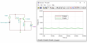
I just managed to have the simulation going down to a drop lower than 1.25V. TBH, I have not figured, what is going on with the simulator sometimes finding or not finding the DC operating point.
Well, I do have regulation down to 0.75V drop as I figured before hands. PSRR is 113 dB.
Another design choice: I do not want a center tap secondary winding. I prefer using a 4 diodes bridge, accepting à 2 Vf drop for a simpler transformer, no un balance issue prone to give some 50 Hz ripple component and a double diode resistance for lower current spikes.
About SMPS, I think there is the good the bad and the ugly. I know a couple that have been tested and found very good for low noise audio, but will not venture elsewhere.
I am not in this case for my microphone preamplifiers design. I only like fairly low drop supplies.
I want the regulator next to the diode bridge and reservoir caps ( no pre regulation ). The low drop I like to have is to lower the pass transistor heating.
I just managed to have the simulation going down to a drop lower than 1.25V. TBH, I have not figured, what is going on with the simulator sometimes finding or not finding the DC operating point.
Well, I do have regulation down to 0.75V drop as I figured before hands. PSRR is 113 dB.
Another design choice: I do not want a center tap secondary winding. I prefer using a 4 diodes bridge, accepting à 2 Vf drop for a simpler transformer, no un balance issue prone to give some 50 Hz ripple component and a double diode resistance for lower current spikes.
About SMPS, I think there is the good the bad and the ugly. I know a couple that have been tested and found very good for low noise audio, but will not venture elsewhere.
Last edited:
Why then worry? If it is 1.25V then it is 1.25V and just calculate with 1.5V to be safe. That is half of the classic regulators so OK. Maybe you should not simulate but just build the thing.
Ah a seventh design requirement. Are you sure it helps to mention all the very specific 7 hard requirements after asking questions and getting input?
Ah a seventh design requirement. Are you sure it helps to mention all the very specific 7 hard requirements after asking questions and getting input?

Indeed, I am at the point I must build.
But I like to have everything fully calculated and hate design by trial and error. My eldest son, says, I am overdesigning.
Yes, I will calculate with 1.5V drop to be safe for the 48v 120mA and 2V drop to be safe for the 30v 400mA.
Two things bother me:
_The 3.3 factor going from output DC Watts to transformer AC VA. I feel this 3.3 is way too much.
_When ordering, how is defined the winding voltages. I know, it is rms, but is it with no load or full load.
I think I saw a PSU calculator on DIYaudio but I do not find it. May be, seen on another site.
An eight requirement: Should work in Australia, as well as in Europe.
Thanks for all your inputs.
Maybe the 3.3 factor is with power amplifiers. I think it is too much for low power stuff.
Talema molded so 100% silent transformers are specified both with and without load. With only 120 mA a 10VA type will give more than its nominal voltage likely a 2 x 18V will give 2x 20 to 21V. You are not going to have a transformer custom wound are you? If you do specify a 240V or even 250V primary winding. I wouldn’t, the molded toroids are both affordable and available in the right voltages and implementation is very simple.
Australia or EU mains voltage do not differ much.
You are plain wrong thinking simulation/calculation is definitive. Reality always wins and therefor sharp calculation also works out pretty well. I disliked the opposite so much that I only do sharp calculation. Trial and error is the other side of the spectrum but it may be quite close to the now used method 🙂 Having various voltages in stock of course helps. And please use rigid mounting of stuff certainly when it is portable stuff or stuff for gigs.
Last edited:
This is a toroid (30VA; 2x18V) mounted on a steel sheet, and this one is placed in the middle of the 2U Galaxy housing - I have 40mm available there. There is still about 3mm of free space above the transformer.
On the other side of the sheet there are diodes, filtering and simple pre regulators on pcb (You can see 4 screws).
Under the transformer is of course rubber.
It is screwed with a 30mm Allen screw to a nut like this or like this.
You can do it directly to bottom cover of the chassis. Simple, stable.
Do you really need regulation for the power section? How about just regulating for the preamp?
My experience with high gain amps say for microphones, is that ripple is of a bigger concern than regulation.
That is easily combated by using an NPN bipolar transistor set up as a capacitance multiplier. Two resistors a transistor set up as emitter follower and a relatively small capacitor on the base gives you wonderful ripple rejection on the supply. The transistor hfe multiplies the capacitance value. With an Hfe of 200 a 100uf cap becomes a 20,000uf capacitor. Those three components are cheap enough you could afford a circuit per section of preamp. Maybe you are building an 8 channel mixer for example - capacitor multiplier for each section. A small T0-93 transistor has sufficient current in this case.
For the life of me, I could not get rid of that last bit of hum using regulators for a discrete op-amp design I made. A capacitance multiplier was 10x as effective at a minimum.
Most class A/B amps just filter the supply as there is very little to be gained from regulation as they reject common mode noise on thier own, It's the high gain front end that will amplify noise. Note in the example you do loose 1 volt of power supply V due to base current and Vbe. So what in a preamp section.
Attachments
- Home
- Design & Build
- Parts
- Toroidal O-core transformer