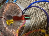
From photo i see toroid has a hole in the middle ,so its no problem to add some turns over existing .Only whats need to be done properly ,is proper insulation of additional winding .
Gotcha.
Any idea what Gauge wire I should use, and once completed and isolated, will this Toroid be good as new (ie for long term use?)
Any idea what Gauge wire I should use, and once completed and isolated, will this Toroid be good as new (ie for long term use?)
Wire diameter of half primary is too small ,current can't rise enough to reach required value ,so winding wire will limit power ,and will heat up .It woud be heat lossy to try get all the power from half primary. Yes , wire additional winding on top ,windings order on iron primary-secondary-primary barely has effect on low frequencies i think .
If you only use “half “ the primary it will be a 500 VA unit. You could add the missing turns to the “shorter” half-primary. Add turns of #14 THHN around the outside, add them in series with the shorter primary. When you have the right number of turns the circulating current will go away. This is a way better situation than having a short between the two halves, at a 1-turn offset. I’ve seen this happen.
From the difference in secondary voltage between the two halves, it looks like more than a one turn difference. That’s a pretty bad screw-up since they are usually wound together.
From the difference in secondary voltage between the two halves, it looks like more than a one turn difference. That’s a pretty bad screw-up since they are usually wound together.
I'm from europe and we use different units for wire diameter . Offcourse there are lots of conversion tables from avg wires to mm2 . So toroid is 1000VA , to simplify and with some overkill 1000W ... Half primary is 500W .Your ac mains is 120v , so wire must be able to work at 4-5A .According to old soviet times enamelled wires table , current density is specified 2A / mm2 ,so you need about 2 mm2 , diameter 1.6mm ,AWG 14 (correct me someone if i'm wrong). Better use too big wire ,rather too small diameter ,if you want long term stability .
Problem with primaries may be different number of turns ,because they are wound one first ,another after it .I have not seen yet a mains frequency transformer ,where a few windings will be wound simultaneously .If they would be wound in such way ,current situation would be not possible ,except one wire ended first and another continued winding .
The temperature rise in a transformer must be measured at the core, not the outside or the laminations.
Measuring the core temperature rise cannot be carried out directly, and so it must be calculated by change of resistance.
I have attached a PDF example of how this is done - the temperature rise in your transformer is probably frightening.
Measuring the core temperature rise cannot be carried out directly, and so it must be calculated by change of resistance.
I have attached a PDF example of how this is done - the temperature rise in your transformer is probably frightening.
Attachments
Thanks, no need to go further, it´s definitely defective. 🙁45 minutes and its up to 50c with the Ambient at 20.1c
With a little effort you can salvage this transformer to full 1000VA rating.Separating them and feeding 120v to each gave no power draw on the bulb, even the slightest, which was different form when they were paralleled...
So I measured the voltage on the secondaries, when powered by Prim 1, I get 40-0-40 on the secs.
When powered by the Prim 2, I get 43-0-43 !!!
So it seems one of the prims has a few extra turns.
So the question I now have is... how can I salvage this toroid, I am sure if I power it with only one Prim, it will not heat up (still to be tested) but what does that mean, is the 1000va trafo now a 500va trafo?
1) You must ADD some turns to Primary 2 (the one which gave you highest secondary voltage).
2) how many?:
a) apply 120V to Primary 1, the "good" one.
b) measure voltage appearing across Primary 2 (the incomplete one)
Do the Math.
If 120V on primary 1 gives you 114V on Primary 2 then you need to add 6V worth of turns to Primary 2
c) determine turns-per-volt-
Wind 10 turns around core, any wire, even plastic insulated lamp cord, by hand, reapply 120V to primary 1 and measure voltage found at test winding.
Don the Math to calculate how many turns needed for missing voltage, 6V in this example but actually what you measured at 2b
d) now you know turns needed, diameter will be same as that used at primary.
3) test phase.
Repeat 2a, measure voltage across Primary 2 in series with new winding.
If you also get 120V, fine.
If you have even LESS than before, added winding is wrong phase, invert its ends.
Might need to add/decrease 1 turn for fine tuning.
4) permanently add just wound auxiliary winding to incomplete one, solder, tape and insulate.
Now you have 2 exact same voltage windings, which can be used series or parallel as you need.
Last edited:
As a test used a small gauge wire to see how much wire I need for the 14ga ( which is what the secs seem to be.
Driving the secs 120 v (approx) I get 155vac on Prim 1 and 147.5vac on Prim 2. That’s a 7.5 vac difference.
9 loops/ turns, gets Prim 2 up to 154.5 vac and 10 turns seems to bump this to 155.6 give or take.
Should I go with the higher ie 10 turns? Is 0.5v difference too much?
Driving the secs 120 v (approx) I get 155vac on Prim 1 and 147.5vac on Prim 2. That’s a 7.5 vac difference.
9 loops/ turns, gets Prim 2 up to 154.5 vac and 10 turns seems to bump this to 155.6 give or take.
Should I go with the higher ie 10 turns? Is 0.5v difference too much?
Attachments

Try to minimise difference itself .When you get only worse by adding and removing one turn .Looks like i can't attach pictures 🙁
Last edited:
So the root cause was unbalanced winding and current flows from one sec to another, inside the toroid? Thats very bad QC...
Try to minimise difference itself .When you get only worse by adding and removing one turn .Looks like i can't attach pictures 🙁
How 🙂
This is where I am. 0.6v difference.
Attachments
So the root cause was unbalanced winding and current flows from one sec to another, inside the toroid? Thats very bad QC...
I guess. I used many from them... 10-12 or so and did not have a problem.
Try to minimise difference itself .When you get only worse by adding and removing one turn .Looks like i can't attach pictures 🙁
I think I got it.
What’s the best way to wrap this? I have tapes. But Kapton or other wraps.
I don't see any current measurements at all, if there is heat generated then there is power, which means current must be flowing. Current measurements would help identify the problem (fed from an isolation transformer to be safe or a current clamp meter), if the imbalance is the issue the primary side current should be lower when fixed and would help prove it.
1) in general that´s the procedure BUT how on Earth can you drive a secondary with 120VAC and get 155VAC on it?As a test used a small gauge wire to see how much wire I need for the 14ga ( which is what the secs seem to be.
Driving the secs 120 v (approx) I get 155vac on Prim 1 and 147.5vac on Prim 2. That’s a 7.5 vac difference.
9 loops/ turns, gets Prim 2 up to 154.5 vac and 10 turns seems to bump this to 155.6 give or take.
Should I go with the higher ie 10 turns? Is 0.5v difference too much?
And 147.5VAC on the other?
PLEASE explain that impossibility before we go on.
Injected 120v on the top and bottom of secs Which are in series ie. 40-0 in series with 0-40. Given the 1.5/1.0 ratio of the prim to the sec 120/(40+40), I was expecting 180v on the prims. I got closer to 155v ( some voltage drop due to 65w bulb limiter in series with mains. So actual Ac to secs might be closer to 110v.
So the voltages on the Primaries are now matching to 0.2v ac. However theres an audible buzz ( 60Hz) now and the Bulb is a very very dull orange. Is this normal? ( Given I am driving lower impedance with mains?)
So the voltages on the Primaries are now matching to 0.2v ac. However theres an audible buzz ( 60Hz) now and the Bulb is a very very dull orange. Is this normal? ( Given I am driving lower impedance with mains?)
Last edited:
- Home
- Amplifiers
- Power Supplies
- Toroid Warming up....