I've been goofing around with an amp design for a while now and am attempting to come up with a power supply that will use parts that I have on hand. I have several large toroidal isolation transformers that I have been wanting to use, but 120v isn't overtly useful here. I'm going to be using 6GC5's for the output, and they are happy at that voltage, but I want to use 6DJ8's in cascode on the front end, and I need at least 180v for those. A little more would probably be ideal. I was considering using a doubler to get that higher voltage, but I thought it might be neat to extend the secondary on one of those toroids to get whatever voltage I need. There is plenty of room for extra windings, and they ran at close to 10A steady-state in the equipment that I pulled them from. I thought maybe I could use the original "tap" on the secondary as the low voltage section and extend the winding to a new tap that would be the high voltage section. Then just have two bridge rectifiers, etc. I'd also have to add a filament winding. What I'd like to know is if that would introduce some sort of issue that I am not aware of. I could in theory wind a completely new winding for the high voltage, but that would be a lot more of a hassle. Possibly extend the original winding for the high voltage and then add a new winding for the low voltage. I'm not sure yet. If this goes well, I'd like to eventually use the rest of those toroids for other amp projects. Do any of you know of any problems I would encounter by doing this? If acceptable, I'm going to build enclosures for the toroids out of stainless steel sheet metal. I have a bunch of it on hand.
I've included a rough schematic to give a better idea of what I'm talking about. Voltages aren't exact here. It's just for illustration purposes.
Thank you for the help. I'd be lost without these forums.
I've included a rough schematic to give a better idea of what I'm talking about. Voltages aren't exact here. It's just for illustration purposes.
Thank you for the help. I'd be lost without these forums.
Attachments

To make a transformer work properly the amount of copper (weight) of the primary winding must equal the secondary windings.
So if say 1lb of copper is the weight of the primary and it makes up 220turns, the secondary may have 400turns but the actual weight of copper should be the same.
Just adding more turns is not the propper way to do it but adding an extra 10 - 15% wouldn't harm the efficiency much.
So if say 1lb of copper is the weight of the primary and it makes up 220turns, the secondary may have 400turns but the actual weight of copper should be the same.
Just adding more turns is not the propper way to do it but adding an extra 10 - 15% wouldn't harm the efficiency much.
It's interesting that you mentioned that, because technically these aren't isolation transformers. They have a 1:1 winding on them, but they also had two high-current 45v windings that went to a very beefy inverter circuit and 5-6 smaller low voltage windings for the electronics. (I salvaged them from Hipot testers that were used in a manufacturing environment to test electric ranges) I removed all of the secondaries (aside from the 1:1) from the core of the transformer I've been messing with. I had originally considered using it as a benchtop isolation transformer for small projects.
Equal weight *tends* to be an economic optimum. It is widely violated at high and low voltages. (Very low voltage's fat wire won't bend well, and one gauge small may be far easier. Very high voltage won't use the 'ideal' gauge because it would be too fragile.)
At DIY profit margins and left-over parts, equal-weight may be moot. I'd certainly pull a 2Watt 6DJ8 off a kilowatt core.
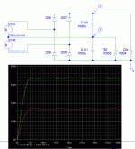
> Attached Thumbnails Toroid Transformer Winding-dual-rectifier-jpg
I fear that in your plan, if you connect the two "grounds" together, smoke will escape.
At DIY profit margins and left-over parts, equal-weight may be moot. I'd certainly pull a 2Watt 6DJ8 off a kilowatt core.
> Attached Thumbnails Toroid Transformer Winding-dual-rectifier-jpg
I fear that in your plan, if you connect the two "grounds" together, smoke will escape.
Last edited:
Yes, just so you don't miss that comment, your schematic won't work.
You will need two isolated secondaries.
You will need two isolated secondaries.
Last edited:
So, perhaps a dedicated winding for each rectifier would be recommended? It worked in simulation but that doesn't mean too much.
Okay then. That shouldn't be too much of a problem. I was just hoping I could save myself some work. The core is way overkill for what I'm working with, but it's what I've got. I hooked up a big 300 watt resistor to it and pulled 225 watts for a half-hour with no issues. It didn't even get warm. That resistor got hot enough to cook on though. I do have a smaller toroid that I may try to modify. It also has some lower voltage windings on it that I may be able to remove. All of these transformers are just taking up space in my shop as it is. I never really considered doing this before but it opens up some new exciting possibilities.
No smoke, just the two outputs with the same high voltage and two diodes in the upper bridge doing nothing.> Attached Thumbnails Toroid Transformer Winding-dual-rectifier-jpg
I fear that in your plan, if you connect the two "grounds" together, smoke will escape.
Mona
This is surely more what you want. The low-voltage supply runs at somewhat low transformer utilization but this transformer is more than tubes need. (And a transformer in the hand beats any "better" iron which has to be ordered and shipped...)
R and C values not critical. More filtering can be added as needed.
R and C values not critical. More filtering can be added as needed.
Attachments
This is surely more what you want. The low-voltage supply runs at somewhat low transformer utilization but this transformer is more than tubes need. (And a transformer in the hand beats any "better" iron which has to be ordered and shipped...)
R and C values not critical. More filtering can be added as needed.
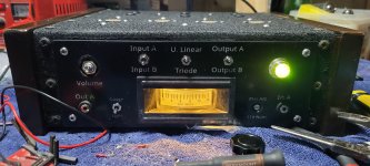
Awesome! That wildly simplifies things. Thank you! And I agree that a transformer you already have tends to be better, especially considering how much some of them cost these days. One for this amp wouldn't be too bad, but I want to look into using two of these toroids later for dual monoblocks running EL34's or something similar in PP. Those transformers would be close to $100 each or even more. And then there's still the issue of OPTs and all the other stuff that one has to get. Edcor is cheaper, but it takes months for them to arrive. And I like the idea of making my own stuff. Below is a pic of my last chassis. I didn't finish it because I kept running into design oversights and decided to start over. The chassis is just that same stainless sheet metal, hammered out over an anvil and then painted with wrinkle paint. It looks a little janky in the photo for some reason, but that meter light is warm white and the wrinkles don't actually stand out so much. Pardon the mess on my bench too.. Either way.. I made templates with a 3d printer so I knew exactly where to drill all the holes for all the tubes, bolts, etc. In the end, it was the wiring that got me. It looked like a plate of spaghetti on the inside. I've since learned how to etch PCBs, so that's how I'm going to proceed with the new design. And I'll try to apply what I learned last time.
Attachments
Last edited:
- Home
- Amplifiers
- Power Supplies
- Toroid Transformer Winding