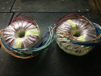
I bought a surplus toroid transformer from E*ay with the primary I needed and a heavy enough secondary for filaments.
I started stripping wire: Fortunately the primary was closest to the core, followed by a high current, lower voltage winding.
I kept checking the voltage while stripping the high current secondary until I got the filament voltage I needed.
I put fiber ( I used automotive gasket material) to give me a smooth surface and electrical isolation for my HV secondary.
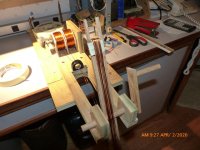
I bought two spools of magnet wire after estimating my current and length requirements, and made a fixture to move the wire pair to a bobbin.
It took several days to wind the secondary: After going around the toroid enough to obscure the fiber, I added a ring of masking tape so I could see and keep my spacing even.
I also added a separate 12 volt winding for control and possible digital features to my future amp.
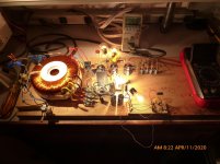
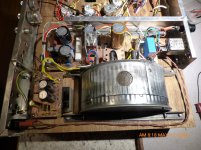
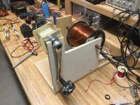
After testing, I enclosed the transformer in a pair of steel heating duct covers for magnetic shielding and to provide a means of mounting.
I started stripping wire: Fortunately the primary was closest to the core, followed by a high current, lower voltage winding.
I kept checking the voltage while stripping the high current secondary until I got the filament voltage I needed.
I put fiber ( I used automotive gasket material) to give me a smooth surface and electrical isolation for my HV secondary.
I bought two spools of magnet wire after estimating my current and length requirements, and made a fixture to move the wire pair to a bobbin.
It took several days to wind the secondary: After going around the toroid enough to obscure the fiber, I added a ring of masking tape so I could see and keep my spacing even.
I also added a separate 12 volt winding for control and possible digital features to my future amp.
After testing, I enclosed the transformer in a pair of steel heating duct covers for magnetic shielding and to provide a means of mounting.
That is a lot of work. I use Kapton tape to insulate the windings.
About how many turns per volt did you get with the windings?
About how many turns per volt did you get with the windings?
Great fun and educational winding transformers.
I learned a bit when I was doing SMPS transformers.
I used bifilar wiring and had problems with high current draw on no load.
It seems you have to be careful to keep bifilar wires closely bound and same length.
I learned a bit when I was doing SMPS transformers.
I used bifilar wiring and had problems with high current draw on no load.
It seems you have to be careful to keep bifilar wires closely bound and same length.
Approx 1 Turn/Volt. As I was using a center tap, it was a bit over 150 turns. I cannot figure out how to post pictures: I uploaded them, but they do not appear. I'm not well schooled on this digital stuff!
I use imgbb website ImgBB — Upload Image — Free Image Hosting to host pictures for me.
Upload your picture and copy the link into your DIYAUDIO message.
Upload your picture and copy the link into your DIYAUDIO message.
Approx 1 Turn/Volt. As I was using a center tap, it was a bit over 150 turns. I cannot figure out how to post pictures: I uploaded them, but they do not appear. I'm not well schooled on this digital stuff!
good job, will be winding my own soon, for the turns per volt of 1, your traffo must be 6kg or more...
this forum lets you host your pictures, just click the go advanced button for that...
i will be using silk tapes and or cotton tapes about 25mm wide, with the silk tapes you have plenty of choices for color, i chose sky blue and black...
Posting Pictures
Tony: I must have done something wrong. Same as initial attempt at pictures. I am trying Nigel's method now.
P1050459 — ImgBB
P1050474 — ImgBB
excess secondary removed😛1050454 — ImgBB
P1050469 — ImgBB
Tony: I must have done something wrong. Same as initial attempt at pictures. I am trying Nigel's method now.
P1050459 — ImgBB
P1050474 — ImgBB
excess secondary removed😛1050454 — ImgBB
P1050469 — ImgBB
Thanks, Nigel
That works!! I got the order wrong, but enjoy all. I will be posting about my amplifier in the Tube Section next.
That works!! I got the order wrong, but enjoy all. I will be posting about my amplifier in the Tube Section next.
Correction to V/Turn
Reviewing my pictures I finally posted, I see it was actually 1/4 volt per turn, and yes, it is a beast.Approx 1 Turn/Volt. As I was using a center tap, it was a bit over 150 turns. I cannot figure out how to post pictures: I uploaded them, but they do not appear. I'm not well schooled on this digital stuff!
I wound my tube output toroid transformer with 1,700 + 1,700 turns primary. It is pretty easy if the core is big and you can use round spool winding shuttle. Re. insulation, there is special heat-shrinking polyester tape specially made for toroid transformers. Most commercial transformers use it. I highly recommend using this tape, and not anything else!
MoeStevens,
It is a good feeling to do a job like that isn't it.
I hope that you put an insulating layer over the final winding. You reallly do need to insulate it. I have used everything from black PVC tape to Kapton on various builds - but the outcome you need is to protect and insulate that final layer of windings.
Too true, a very good feeling. I had a 500VA dual secondary at 60Vac each and wanted 50V. But only the tail end of one secondary was visible. So I wound a pair of 20 turn extra secondaries and wired them contra. That is the 10V was subtracted from each original by the additional reversed magnetic flux. Theory said it should work and blow me down, it did.
Microwave oven transformers push the flux density to the max and are about 1V/turn, so I expect much less. I often put a 9VAC aux winding on toroids to power the protection circuit and relay.
I use imgbb website ImgBB — Upload Image — Free Image Hosting to host pictures for me.
Upload your picture and copy the link into your DIYAUDIO message.
So many previous posts with good stuff are now unusable because folks used all kinds of document hosting services that are now defunct, rather than uploading to diyAudio.
Please upload folks! It’s not hard to do. Do not provide a link! Upload.
I have been with imgbb for years with no problems.So many previous posts with good stuff are now unusable because folks used all kinds of document hosting services that are now defunct, rather than uploading to diyAudio.
Please upload folks! It’s not hard to do. Do not provide a link! Upload.
Seems a shame to use up DIYAUDIO site web space which costs them money.
Also, if for some reason you want the picture removed you can with imgbb but not with DIYAUDIO.
I wound my tube output toroid transformer with 1,700 + 1,700 turns primary. It is pretty easy if the core is big and you can use round spool winding shuttle. Re. insulation, there is special heat-shrinking polyester tape specially made for toroid transformers. Most commercial transformers use it. I highly recommend using this tape, and not anything else!
Ive been having trouble finding that *tape*. The best the guys at Tape-rite have been able to get for me was 1 mil thick, which is a little thin and makes me go through it like water. Any ideas where I can get the 3 mil stuff? I can get just about *anything with adhesive* but without is pretty rare.
I also use the yellow adhesive version (typically used for securing windings on SMPS trafos, available from the usual distributors) to hold everything together once it’s wound. And to insulate between layers on EI builds. The adhesive isn’t a problem on EI’s.
I’m thinking it might be a good idea to do several polyurethane dips on some of the ones I’ve “created” to further protect the windings. In case the amplifier racks get dropped of a truck or otherwise mishandled. This latest one is over 30 pounds each with a butt load of windings for a class H solid state. In case you’re wondering, the amp uses *both* so it’s heavy.
I’ve been thinking about doing tube trafos this way too, but been put off by the sheer number of turns required. I use a hand shuttle for these big ones of course - with quad filar #12 you pretty much have to - and you’re done winding in about an hour. At least each set of secondaries is relatively short (under 100 turns). Tube amp power or output trafos will have many times that. Moe, can you share any details about your winding shuttle? It looks pretty niiiiice.... I have made my own EI winder, so it may be time to build one for toroids.
Attachments
Winder
wg_ski;6542810 Moe said:MoeStevens,
It is a good feeling to do a job like that isn't it.
I hope that you put an insulating layer over the final winding. You reallly do need to insulate it. I have used everything from black PVC tape to Kapton on various builds - but the outcome you need is to protect and insulate that final layer of windings.
The winding shuttle has to be designed for the transformer being considered:
First, the determine total amount of wire needed. There are calculators on the internet for cross sectional area. Then, since the aperture of the core will decrease as you add turns, that must then be considered. The length of the shuttle is finally dependent on the restrictions imposed by the former. My shuttle was 15 inches long by 1 1/4 wide. Each notch was 3/4 by 1 3/4. The picture I posted is probably worth 1000 words, but what is not apparent is the non-rotating spacers, spring and bolt from my junk box to provide tension on the spools of wire: When drawing it off it will be "hurky-jerky" and with no tension the wire will backlash. The axle is screwed to the shuttle, and by spreading the wires can be removed after you are done loading it.
The base with the U-shaped opening is then reused as a platform for winding.
Finally, don't get sleepy while winding or you my drop the shuttle, tangle the wire, and break off an ear of the shuttle (been there, done that😡)
Finally, I salvaged the tape used by the factory, and wound it back as well as I could, securing it with masking tape. The duct covers were lined with a bitumen tape used to seal roofs, windows and doors, and provides cushioning for the winding. One of the duct covers was slightly enlarged by hammering flat the wrinkles, and the two were spot-soldered together with my "Big Bertha" soldering iron.
I consider myself lucky that no audible hum is coming from the transformer even under full load. Dipping it in varnish without a vacuum chamber would not be really effective.
thanks Tony. I've gotten a virus by clicking on an external picture hosting site, I don't do that anymore. Besides, most sites wants your birthdate, address, drivers lic #, credit card number for their "free" services. To put picture on diyaudio, click "go advance", browse hard drive for picture file, upload. Right way to do it. Every edit requires going advanced again or the pictures disappear.posting MoeStevens photos....
Don't understand the winding jig. What good is a coil 14" long by 1" wide by 1" thick? Toroids are 3/8" to 1.5" in diameter in a circle 1 to 6 inches, the ones I've salvaged. Toroids don't have a hatch to slip a prewound coil over them. EI transformers do.
Last edited:
- Home
- Amplifiers
- Power Supplies
- Toroid Power Transformer: How I wound my own.