Is it worthwhile to install a copper gauss band on a power toroid (Antek). I've done some searches but have found nothing conclusive.
I realize toroid's don't radiate as much junk as an EI type but I have had issues in the past with noise.
Thanks!
I realize toroid's don't radiate as much junk as an EI type but I have had issues in the past with noise.
Thanks!
Doesn't the Antek have a Gauss band already?
I could have some benefit, but I would look elsewhere first if you're trying to hunt down hum issues.
Tom
I could have some benefit, but I would look elsewhere first if you're trying to hunt down hum issues.
Tom
I haven't had any issues with Antek's transformers, large or small, and to the best of my knowledge they don't have a gauss shield, but some models do have an EMI/RFI shield between the primary and secondary. I would make sure there aren't any internal loops in the unit, or external loops from multiple grounds causing the noise problem first.
Sometimes, if the problem really is from magnetic leakage from the transformer it can be reduced by rotating it to a different orientation, or moving it further away from sensitive components or circuits.
Mike
Sometimes, if the problem really is from magnetic leakage from the transformer it can be reduced by rotating it to a different orientation, or moving it further away from sensitive components or circuits.
Mike
I have used this method a couple of times, listening while moving/turning transformer and cabeling.
You get immediate response, very intuitive .
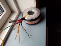
And the band does help, here is my latest used trafo "improved" with band, it's for the p3a.
You get immediate response, very intuitive .
And the band does help, here is my latest used trafo "improved" with band, it's for the p3a.
Attachments


For a toroid a regular Gauss band is almost useless, because the stray fields are aligned with it; it can have an electrostatic shielding effect, but that's about it.
The Gauss band equivalent for a toroid would have to be a continuous, flattened copper sphere encompassing the whole transformer, which not very practical.
The alternative is a GOSS band, and this will work since it is ~aligned with the bulk of the stray fields
The Gauss band equivalent for a toroid would have to be a continuous, flattened copper sphere encompassing the whole transformer, which not very practical.
The alternative is a GOSS band, and this will work since it is ~aligned with the bulk of the stray fields
One more point: the above applies to correctly wound transformers: each individual winding needs to have an even number of layers, and the winding direction needs to be reversed at the end of each odd layer.
Failure to do so will create "ghost" turns, meaning non-zero external field, magnetic leaks and leakage inductance.
To determine if a transformer is properly built, you can wind a dozen turns of insulated wire around the periphery, where the Gauss band would sit, load the transformer to its maximum and see if a voltage appears across the auxiliary winding.
If a non-negligible voltage appears, it means that the construction is incorrect, and in this case, a Gauss band can be used as a band-aid, to mitigate the problem, but the best option is to start with a good transformer
Doesn't the Antek have a Gauss band already?
The AS- series do, yes.
Yes it's an AN series with the shield between the primary and secondary.
I was thinking a band around the outside would help mitigate any residual radiated noise.
It's for an Aleph J and hasn't been installed yet. If it can't hurt I may do it.
Maybe GOSS was the term I should have used.
As always, I appreciate the input. Gest regards, Mark
I was thinking a band around the outside would help mitigate any residual radiated noise.
It's for an Aleph J and hasn't been installed yet. If it can't hurt I may do it.
Maybe GOSS was the term I should have used.
As always, I appreciate the input. Gest regards, Mark
From an electrostatic POV, it will always help provided it is grounded, and the thickness or material doesn't matter.I was thinking a band around the outside would help mitigate any residual radiated noise.
To determine whether a Gauss band is required, wrap one or two dozen of turns around the transformer, and measure the AC voltage, loaded and unloaded. You should see <0.2mV in all cases.
In some instances, a voltage can appear or disappear with the load, depending on the geometric configuration of the primary and secondary, but in any case a Gauss band is required because you cannot predict the loading.
When a transformer is properly built, the voltage will always be 0, and a Gauss band is useless.
For 50/60Hz, a Gauss band needs to be substantial, like 0.5 or 1mm because the stray field is mostly the fundamental frequency, unlike other types of construction like EI.
A GOSS band is always useful, to absorb small winding irregularities, and it is not incompatible with a Gauss band
each individual winding needs to have an even number of layers, and the winding direction needs to be reversed at the end of each odd layer.
I don't get it. For my knowledge nullifying the h-field will make the transformer useless. Have you any links to this theory?
+1For a toroid a regular Gauss band is almost useless ... The alternative is a GOSS band, and this will work since it is ~aligned with the bulk of the stray fields
Also, the voltage induced due to the stray magnetic field, proportional to BAω, is significant only at high frequencies and not at 50/60Hz. Even if B is really large (e.g. in the vicinity of motors etc.), the stray voltage can easily be kept small by reducing the loop area A.
Do manufacturers usually do this? I have often wondered because it's clearly better in theory but I've never seen a transformer manufacturer claim to do this.One more point: the above applies to correctly wound transformers: each individual winding needs to have an even number of layers, and the winding direction needs to be reversed at the end of each odd layer.
Failure to do so will create "ghost" turns, meaning non-zero external field, magnetic leaks and leakage inductance.
I expect that if they took the care to do this then they would advertise the fact, but maybe it's just assumed, or do they just wind on as many turns as needed and that's what the customer receives?
If anyone wants to send me a failed toroid I would love to take it apart to check, PM me.
My first idea was that it would be worse as the transformer load increased, then I wondered if the increased current in the secondary would create a field that cancelled out the primary, and maybe there would not be a substantial increase, maybe even a decrease.To determine if a transformer is properly built, you can wind a dozen turns of insulated wire around the periphery, where the Gauss band would sit, load the transformer to its maximum and see if a voltage appears across the auxiliary winding.
If a non-negligible voltage appears, it means that the construction is incorrect, and in this case, a Gauss band can be used as a band-aid, to mitigate the problem, but the best option is to start with a good transformer
Then I decided it's complicated, the primary could have an odd number of layers and the secondary could be even, so no cancellation, or secondary could be odd, in which case it could reinforce or potentially cancel.
I think this explains your comment below
....In some instances, a voltage can appear or disappear with the load, depending on the geometric configuration of the primary and secondary...
At least, I think that's how it could work but it's not clear in my mind, do you have any data, or clarification on this?
I don't get it. For my knowledge nullifying the h-field will make the transformer useless. Have you any links to this theory?
Try this https://en.wikipedia.org/wiki/Toroidal_inductors_and_transformers
The even number of layers cancels the loop current that causes external (stray) field.
Best wishes
David
Last edited:
This isn't absolutely necessary. The magnetic stray occuring in parallel with the mounting bolt can also be avoided in non-even layered windings with an extra turn along the toroid's circumference beneath the winding and wound in the opposite direction of this winding's proceeding, see https://en.wikipedia.org/wiki/File:Toroidal_Inductor-Simple_with_Return_Wire.JPGOne more point: the above applies to correctly wound transformers: each individual winding needs to have an even number of layers, and the winding direction needs to be reversed at the end of each odd layer.
Best regards!
Some do it, or at least use the expedient described by Kay: I have measured a number of samples, and a little more than half have zero external field under all conditions.Do manufacturers usually do this?
Some have a field when unloaded, others when loaded, or both. It depends on the arrangement of the layers of the primary and secondary
I even doubt that most manufacturers are aware of this phenomenon. Have a look at the German Wikipedia entry on toroids. It isn't even mentioned there.
Best regards!
Best regards!
I appreciate all the responses. I've actually learned a few things about transformer construction.
I guess what prompted me to ask the question was the fact that turning a toroid in the chassis can mitigate noise.
It's obviously radiating a magnetic field or inducing it into the chassis itself?
I apologize for the simple questions. Guess I need to do some reading. I believe the Anteks are great for the price. I've used many.
Once again I appreciate all the thought provoking posts!
The effect of the placement of the transformer is completely unpredictable a priori.
Look at this example, where the chassis carries the perturbations much further:
https://www.diyaudio.com/community/...r-hum-problems-the-humboy.378178/post-6816214
At times, it could have the opposite effect, and contain stray fields in the vicinity of the transformer. Magnetic problems are fiendishly trickiy and un-intuitive
This doesn't work as well, the extra turn does not coincide with the effective centre of the coil current so the field doesn't cancel as completely as it does with a return wind.This isn't absolutely necessary. The magnetic stray occuring in parallel with the mounting bolt can also be avoided in non-even layered windings with an extra turn along the toroid's circumference beneath the winding and wound in the opposite direction of this winding's proceeding,
I actually made a toroid inductor and put the return loop inside the coil as an experiment, and that worked as perfectly as I could measure.
Best wishes
David
Please have a close look at the picture that I linked in #14. If necessary, read the Wikipedia article. As I see it, the return wire actually is inside the winding.
Best regards!
Best regards!
- Home
- Amplifiers
- Power Supplies
- Toroid gauss band