The indicator shows it's locked onto a signal, relay clicks in but all I have on analog out is a very faint crackle that pulses to the music.
Opening this little gem up I found the -15V unreg dead (+1.6V at 3-pin regulator IN). The output stage op-amp needs the ±11V regulated but is only getting the + supply.
This could be an easy fix if I had a schematic of if I knew more about switching power supplies.
An email to Topping has gone unanswered for several days.
Anyone just happen to have this schematic?
If you have minimum skill don't need schematic. Simply, remove the burned regulator, and measure both input and output terminals at the PCB, with the set powered off, with a DVM in the diode position. Check both polarities at both terminals (Again, without power source and with the reg's removed). If any of the measurements is abnormal (Say, less than 400mV), search for more damaged components (Diodes, transistor, resistors and IC's). Rarely a cap shorted.
Last edited:
As I said, it's the unregulated switching-mode (-) supply that's toast. The regulator chips are fine.
I don't know which components are part of the switching PS, vs all the DAC circuitry.
My "minimum skills" are all linear & analog.
I don't know which components are part of the switching PS, vs all the DAC circuitry.
My "minimum skills" are all linear & analog.
OK, Rarely a SPMS has a fuse in their outputs. So, there are few thing to check. Firstly, the rectyfing diode for the negative output. In Flyback type, only one diode per output. In Forward type, two diodes: one from the trafo's secondary, and one from this point to ground (the freeweeling diode), so two diodes to measure. For half and full bridge (Rarely at those power levels) each output needs 2 or 4 diodes. Also measure the choke connections for the last two options (Flyback need cap input filter, the other, choke) and finally a capacitor leaky or shorted. So, no need for too complex instrument, a DMM and a current limited power source (a filament lamp in series with one wire of the power cord) during tests. Keep attention to live circuitry inside the SMPSU, most of them has capacitor discrharge circuitry, but not all of them.
I have ±15 available at my bench so I threw caution to the wind and jumped gnd and -15 and immediately music came from my test receiver.
I'm thinking that proves 2 things:
The LM337 regulator is fine, and whatever is immediately before it isn't shorted. My PS was only putting out 16mA to feed the 337 & op-amp. It does make me wonder why 1-amp regulator in a TO220 package was chosen (and bent over to fit the case) over a 100mA version in a tiny TO92 package.
Can you take a couple of pic for the PSU with the cover(s) removed, only the PCB and both sides (Top and bottom)? Perhaps I can help viewing some components in the PCB. I work repairing industrial electronic equipment and in very few cases I have the schematic, so reverse engineering helps me a lot.
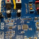
According to the picture, the -15V unregulated supply seems to be generated by the component marked Q6 on the PCB. Check D2-D3 diodes and the ceramic capacitors next to them. There is a component marked L5 next to Q6: this chip could be a flyback supply but the negative supply may also be implemented by a charge pump. The markings over Q6 will give a clue. Any issue on this kind of low-power switching IC-based power supply is usually trivial to fix. If you are unable to find the fault or don't have time to investigate the circuit througly, you may also bypass the whole thing and fit a miniature dc-dc SMPS module with negative output, taking the input from the main positive supply.
pcan,
I really appreciate your insights here.
I thought Q6 might be worth looking at. The pcb foil is heavier there. It's marked IRP807G. I can't find anything online by that number.
The "IR" has a diode icon between, which makes it the logo for International Rectifier. I couldn't find anything on their website either.
D2 checks OK but D3 doesn't conduct. I thought that was part of the +15 side?
L5, 6, 8 I assumed were chokes. All conduct ~1.5 ohms.
By the look of it and the way connections are arranged on the visible pads, Q6 may be a dual mosfet such as IRF9389; check for a "F9389" mark. If one diode is open, replace it and test again. The IRF9389 itself may be faulty, or one of the high capacity multilayer ceramic capacitors (C56, C57, C58, C59, C60) could be shorted.
Replaced D3 with a 1N914 and the PS now works.
Any problem using a "signal diode" in a 16mA -15V supply?
Any problem using a "signal diode" in a 16mA -15V supply?
By the look of it and the way connections are arranged on the visible pads, Q6 may be a dual mosfet such as IRF9389; check for a "F9389" mark. If one diode is open, replace it and test again. The IRF9389 itself may be faulty, or one of the high capacity multilayer ceramic capacitors (C56, C57, C58, C59, C60) could be shorted.
You DO know your stuff! "F9389" is also on the markings.
- Home
- Source & Line
- Digital Line Level
- Topping D30 nearly dead