BACKGROUND
I have a Topas Line 2 power conditioner that has never
worked since I've had it. I've had a tech look at it and
they couldn't help. That was about 15 years ago.
Now, I'd like to get this thing going and use it for
filtering test equipment.
SCHEMATIC NEEDED PLEASE
Anyone have a schematic for one?
I'm guessing the problem is with the logic chip/controller
or one of the triacs.
Last edited:
Hi Sync,
Does it make a deep buzz or growling noise when you plug it in? These are a saturable core reactor (transformer). They can put out almost a square wave at times, depending on load I guess. There is typically a capacitor, looks like a motor run capacitor, on one winding that saturates the core. From there the voltage will be pretty darned stable. These units do tend to get very warm, and they do make a lot of noise. I'm not sure if you would want to use it for your audio system.
-Chris
Last edited:
I have a couple of 10kva Topaz units that were used in my employers computer room in the early 80's. The power there was atrocious and the minicomputers had a low tolerance for noise and wandering voltage. I can attest that they were very noisy. I had one hooked up next to a subpanel in a garage and I ran a 240 line to my music room, and it was very nice. I have since always tried to run 240vac to my system and use several smaller stepdowns to provide balanced 120vac. The key to these Topaz units is putting them somwhere that the noise won't cause problems. I hope to hookup one of my units in my current garage. I have a box where I can break a 30 amp circuit to insert the Topaz and provide power to an almost completed music-first HT room in an adjacent building.
Skip
Skip
I was going to hook up some test equipment to it and see if I could
get a lower electrical noise floor and more stable 120V.
I assume you were talking about physical noice of
the unit.
get a lower electrical noise floor and more stable 120V.
I assume you were talking about physical noice of
the unit.
Just fired it up, started making the noise, so I adjusted the cover and noise stopped.
Turned off, got a 100 watt drop light and variac to adjust the incoming voltage.
Turned them all on and started with the variac. Nothing through 120V.
Then at 130V, it started spitting. Turned off, removed cover,
tried it again around one of the base of the control board it smoked.
Turned it off unplugged everything.
Stinking up the whole house now. Just a tad
bit of magic smoke has been let out.
Can you post a picture of the insides? It sounds as if that one is a UPS, but it isn't supposed to be. Also, I think they like to be loaded. Hi AC voltage would tend to run the capacitor harder on a saturable core reactor.
-Chris
-Chris
Yep, let me find my two wheel dolly,
I'll pull it outside and blow it out, with
some air.
Also finally found one of the camera's charging
cords...no easy feat around my household with
a terrible two's kid running around.
There aren't any batteries associated with this
so I'm guessing just a straight line conditioner.
In the mean time, let me find a pic that I can link to.
This thread is about the Topaz Line 2 Power Condition from Square D.
Specs:
It is model: 02406-01P3
Output Pwr: 1k VA
Input Volts: 120
Output Volts: 120
Input Current: 12.8 A max.
Frequency: 60 Hz
Fuse: 15A.
Problem:
The unit power's on, but there is no output power.
Pics in the following post.
Specs:
It is model: 02406-01P3
Output Pwr: 1k VA
Input Volts: 120
Output Volts: 120
Input Current: 12.8 A max.
Frequency: 60 Hz
Fuse: 15A.
Problem:
The unit power's on, but there is no output power.
Pics in the following post.
Topaz Line 2 Power Conditioner Pics
Here is the unit's front panel:
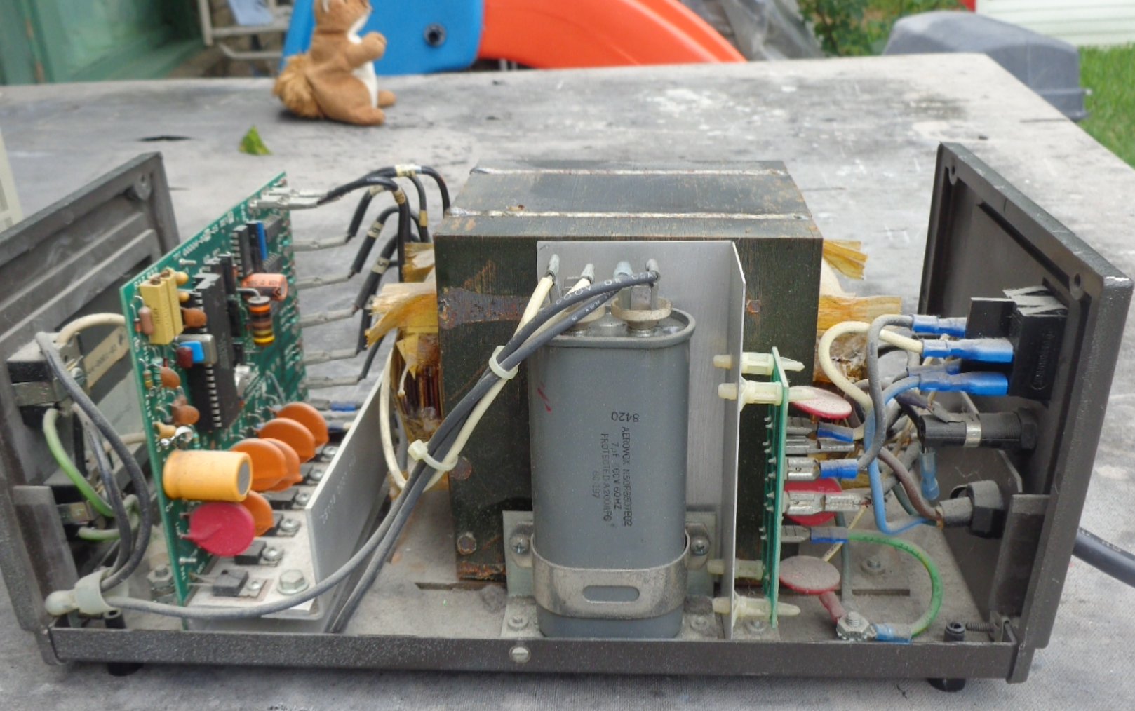
Here is the side view:
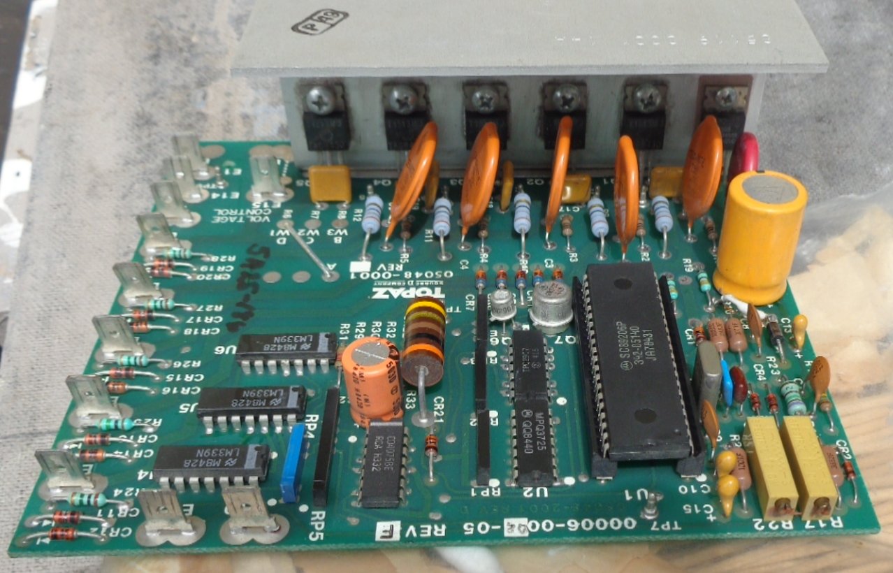
Boar view follows:
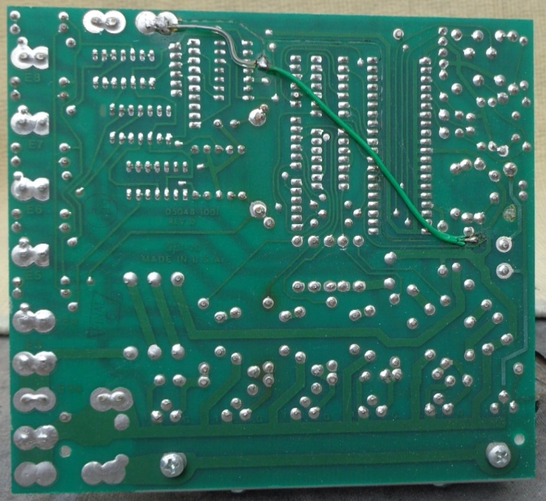
Here is the Board Trace View:
Here is the unit's front panel:
Here is the side view:
Boar view follows:
Here is the Board Trace View:
Hi Sync,
See that gray capacitor in the side view? That is the one used to saturate the core. This unit looks like it was born in 1984.
Is it possible this model has AC power factor correction? That's the only reason I can think of as to why it has circuitry inside. Could also be adjustment for the input voltage range. Time to start going through the features for each model of conditioner. This is well outside my area of expertise.
-Chris
looks like it might be tap selectable using triacs. you could start by checking DC supply for the digi controller and analog sections. After afew basic trouble shooting and visual inspections youll need a schematic to dig further.
get the device data sheets and check DC power at the Vcc pins. It's a comfort on repairs like these that the unit did work before, so detective work as usual.
get the device data sheets and check DC power at the Vcc pins. It's a comfort on repairs like these that the unit did work before, so detective work as usual.
Last edited:
maybe not PCB Rev F and still jumpersIt's a comfort on repairs like these that the unit did work before, so detective work as usual.
Anatech, Yep, I gathered the cap was for saturation on those, 7uf at 660 VAC.
Not a really huge cap though, but plenty tough.
Infinia, As long as I've had it, about 15 years, it's never worked.
I could never get a schematic for one. The company when I contacted
them told me that I could send it in for service, only after they looked
at it would they give me any kind of estimate. Shipping would have
been about twice what I paid for it.
Almost free, I think it was $25.00 Always hoped I could
figure out how to get it working.
Maybe they have a replacement board for cheap.
Oh, and I did find an additional wire like the clear insulated wire
about 3.5 inches long loose in the bottom.
Thinking, yes, Rev F and still jumpers. Also looks like some traces
didn't quite come through from the board maker.
Last edited:
I wonder who the market was for these? minicomputer data centers from late 70's perhaps. seems it would be better to have an electrician in to upgrade the branch circuit, a transformer by itself just adds more drop.
I don't know what the market was for these, sounds reasonable, perhaps minicomputers.I wonder who the market was for these? minicomputer data centers from late 70's perhaps. seems it would be better to have an electrician in to upgrade the branch circuit, a transformer by itself just adds more drop.
Yes, I've had electrician in, no more room for another circuit.
Actually, not enough room to upgrade the wiring that already there
with out major problems.
Not sure how an electrician would upgrade that branch circuit?
If I could find another control board, that might help.
Hi Sync,
Well, it is a plug in unit, isn't it? You might want to play with it before making any long term plans.
These things were usually designed into equipment as part of the power supply. The ITT system 3100 had two of those things for each tower. One system could comprise two towers. Imagine 4 of those power supplies humming away!
I had a smaller system 3100 for my shop. It was impossible to get anything done in the same space as the phone system. I was both hot and loud. That was finally the reason we got rid of it. It was a nice phone system to use though. Who knew in a few years I'd be maintaining them!
I managed to snag a 25 A, 14V power supply using the saturable core transformer. I used it for car audio repair. One thing it did was regulate the output really well. I didn't need an electronic regulator for that supply. I don't know if I would run my audio gear off it though. As I recall it did not have a sine output, more like a soft shouldered square wave. Yours might be different, but I suspect not.
-Chris
before computers used SMPS, they used linear regulators as most logic was +5V @high amps, these things provided tighter line voltage regulation, so helps maintain some sensible heat management and PSU efficiency for those days. gone way of dodo birds, cart em off to the scrap dealer.
Last edited:
Gentlemen,
For now I don't have an output at all.
Interesting if it had a rounded square wave output.
For now I don't have an output at all.
Interesting if it had a rounded square wave output.
- Status
- Not open for further replies.
- Home
- Amplifiers
- Solid State
- Topaz Line 2 Power Conditioner