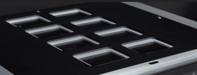
I am thinking about using a black aluminum mesh on the inside of an aluminium enclosure under a large hole to provide good ventilation for an amplifier. Please see picture for the idea. Does anybody have any tips on how such a mesh might be fixed to the inside of the top cover? In particular, it shouldn't rattle or be easily pushed inwards or take up too much space inside the enclosure. Thanks!
Attachments
JB Weld 8272
Make a long snake and apply around the hole, push the mesh on and let cure
Make a long snake and apply around the hole, push the mesh on and let cure

in every amplifier case I built, the top cover is cut from a sheet of perforated aluminum and supported by L-shaped aluminum profile.
See my Krell KSA-50 clone mono-blocks here: https://www.diyaudio.com/community/threads/krell-ksa-50-pcb.31077/page-445#post-5264496
See my Krell KSA-50 clone mono-blocks here: https://www.diyaudio.com/community/threads/krell-ksa-50-pcb.31077/page-445#post-5264496
Even though you're probably not going to submit your build for an electrical safety certificate examination/approval, it's not a bad idea to keep the regulations & standards in mine as they're based on practical situations - one of them specifies the size of the openings that might allow finger access to electrical mains wiring and possible electrocution and from memory, it's about 6mm (square/round/etc) - not sure of this nowadays means 1/4" physical sized object/finger/etc access to any potential mains electrical hazard but it's something to keep on mind - I generally add secure covers/seals/heatshrink/etc over any bare mains contacts or terminals as a routine build and get a bit fanatical about any liquids near same gear but on the other hand, wide open mesh/cutouts is great for cooling and power supplies and can look quite neat.
Er, no, that will come off with heat and time, leaving a nightmare of sticky glue to cleanup... Also electrical standards require all metal parts of the case to be securely earth-bonded to each other, so it should be bolted with crinkle-washers or spot-welded and tested for continuity under high current load (simulated actual earth-fault).Industrial heavy duty double sided tape
On my 1964 BELL 2420 cover - which had NO vents ! - I installed two air conditioner grids :
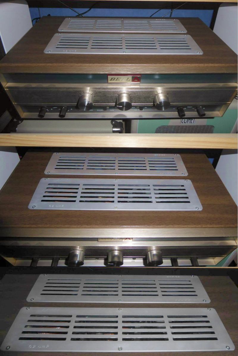
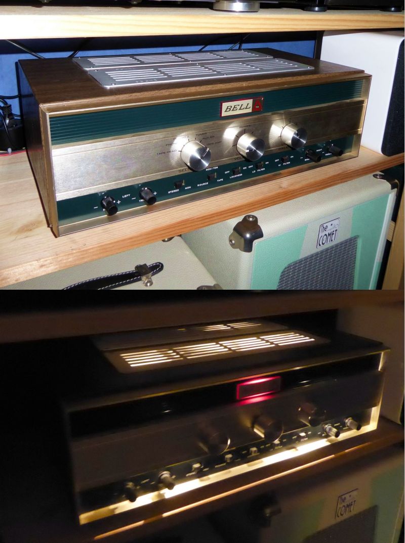
You guess that the tubes rendered me happy "cool-instead of warm" thanks !
I simply cut the openings in the top with a jigsaw, and drilled 6 holes per vent to fix them in place.
T
You guess that the tubes rendered me happy "cool-instead of warm" thanks !
I simply cut the openings in the top with a jigsaw, and drilled 6 holes per vent to fix them in place.
T
Thanks everyone for your suggestions. Lots to think about there. The earthing thing is pretty important as is the slot opening size. We don't want kids using the amplifier as a money box 🙂 Seems like the ideal solution is aluminum welding, but it doesn't look easy and I don't have this equipment. Countersunk screws seems like the best diy option. I was also thinking I could place a thin perforated sheet underneath the top cover plate which would be held in place by the top cover plate screws, but this might rattle in the middle unless secured.
Anyone tried 3d printing a high temperature plastic vent?
Anyone tried 3d printing a high temperature plastic vent?
An option may be to spot weld the mesh to the cover. Not done it myself but search the Internet. Two pieces of copper, a battery and car or motor cycle solenoid is all that's needed .... but practice first.
BUT high temperature silicone sealant would do it but not sure how you guarantee the mesh is electrically connected to the panel.
BUT high temperature silicone sealant would do it but not sure how you guarantee the mesh is electrically connected to the panel.
There's plenty of those 2 part high strenth glues around to fasten the mesh/vents in place - most of it cures quite quickly too and pretty impervious to long term heating - there are some versions that are electrically conducting but I'm more comfortable with at least one physical/mechanical connection for metal mesh like small allan key countersunk screw(s) etc
Look into AlumiWeld. They're low heat aluminum "welding" rods (actually more brazing or soldering) that allow you to bond aluminum using only a standard propane torch. There are other similar products. "Project Farm" on youtube has a comparison of the different products, IIRC. See my post here about using it for my first ACA build: https://www.diyaudio.com/community/threads/aca-concept.267517/post-4253259
Can you assemble the top in layers?
This is what I did with my very modified eBay DIY chassis.
A full layer of perforated aluminum screen sits on the top of the chassis.
A second frame layer over the screen is made from the original solid aluminum plate top.
It can easily be cut by using a cheap picture frame as a guide with a router using a carbide bit.
Just a note…since there are concerns about ventilation, rattling and grounding.
If you look closely you will see there is a cooling system I had to install in my amp using additional heat sinking and fans in order to run the amps at the current I wanted (about 1.8A). The chassis was a bit small for that to begin with…approximately a 4U/300.
There is a pair of 3” Noctua fans attached to the bottom of the perforated screen top that I power off of a voltage regulator so that I can tune the speed of the fans to operate silently.
The cooling system is monitored and run by a digital thermostatic relay. It is affective at maintaining the temperature range I preset.
I have never had any vibration noise problems with this top plate design.
Since the entire chassis (except face plate) and sandwiched top plate of the amp are made of aluminum and held together securely with hardware there is no issue with grounding either.
Top job! Seems like Babelfish! Logo is creative! Which mono-blocks are adjoining to BF?Can you assemble the top in layers?
This is what I did with my very modified eBay DIY chassis.
A full layer of perforated aluminum screen sits on the top of the chassis.
A second frame layer over the screen is made from the original solid aluminum plate top.
It can easily be cut by using a cheap picture frame as a guide with a router using a carbide bit.
View attachment 1404179View attachment 1404180View attachment 1404181
Thanks…yes that’s my Babelfish 2J that I built a pair of for bi-amping my various speaker experiments.
I had to get creative with the logo so as to not step on ZM’s toes but also give credit and show them off 😉.
No CNC in my garage. I have an ancient Logan lathe and a cheap bench top mill. So I made a logo frame from some aluminum pipe and then got creative with LEDs from behind a design I printed out on some japanese washi paper.
The little monoblocks are my beloved F2J clones. They are still one of my favorite amps…currently in use daily with my Kirishimas.
That would be ideal during manufacturing before finishing, but if the enclosure is already finished, then it would leave a spot weld mark on the outside.An option may be to spot weld the mesh to the cover.
That's a great point. These can be treated as 2 separate problems. 1. Fixing the mesh. and 2. Grounding the mesh.There's plenty of those 2 part high strenth glues around to fasten the mesh/vents in place - most of it cures quite quickly too and pretty impervious to long term heating - there are some versions that are electrically conducting but I'm more comfortable with at least one physical/mechanical connection for metal mesh like small allan key countersunk screw(s) etc
That's a great idea and a very impressive execution! Especially cutting out the big holes and making the clean edges. I'll have to look into this.Can you assemble the top in layers?
This is what I did with my very modified eBay DIY chassis.
A full layer of perforated aluminum screen sits on the top of the chassis.
A second frame layer over the screen is made from the original solid aluminum plate top.
It can easily be cut by using a cheap picture frame as a guide with a router using a carbide bit.
- Home
- Design & Build
- Construction Tips
- Top cover aluminium grill/mesh attachment