im on my way to finishing a preamp but the gain is too high could this be because the filament voltage is above 7 when it should be about 6?
thanks
thanks
How much is too much ? Emission will be higher with increased heater voltage but not *that* much. higher.
You can use series resistor, a diode (if you're using DC heater supply) or two diodes (if you're using AC heater supply) to drop the voltage to 6.3V.
You can use series resistor, a diode (if you're using DC heater supply) or two diodes (if you're using AC heater supply) to drop the voltage to 6.3V.
Does this preamp use feedback? What is the schematic of the preamp?
Filament voltage does need to be lowered using a method as Arnulf suggested.
Filament voltage does need to be lowered using a method as Arnulf suggested.
You might be killing the life of the heater by using a higher voltage !
For modern day applications I think most tubes without feedback could give you much higher gain than required. Negative feedback could reduce the gain depending on your circuit.
If I were you I'd try to pick a tube ( for example) that can give lower gain like say a 12B4A than a 6DJ8 and avoid any feedback scheme.
If you post your circuit you might get more accurate replies !
If I were you I'd use a resistor to drop filament voltage, and use degeneration on the gain stage to reduce the gain.
I.e. remove cathode bypass caps and possibly increase cathode res value (with a bridge for the grid bias as required.)
I.e. remove cathode bypass caps and possibly increase cathode res value (with a bridge for the grid bias as required.)
the gain is way too high, i can only turn the volume up about 30% and then it starts to distort. it doesnt use feed back it is a dual paralleled single ended triode with a cathode follower.
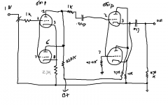
here is the schematic of one channel, the pot is 100k
here is the schematic of one channel, the pot is 100k
Attachments
With a tiny fraction of a milliamp running through your cathode follower, it's not likely to perform well...
This surely is a waste of tubes ... split it up and make it two separate channels or change the topology. If you intend to go the second route, have a look at Broskie's "Aikido" stage - 4 tubes put to a much better effect.
This has nothing to do with the filament voltage, it has everything to do with wrong solution to a problem. If you can desribe what you're actually trying to accomplish (besides building a tube preamplifier, of course 🙂 ), I'm sure we'll be able to come up with a more suitable solution.
This has nothing to do with the filament voltage, it has everything to do with wrong solution to a problem. If you can desribe what you're actually trying to accomplish (besides building a tube preamplifier, of course 🙂 ), I'm sure we'll be able to come up with a more suitable solution.
This surely is a waste of tubes ... split it up and make it two separate channels or change the topology. If you intend to go the second route, have a look at Broskie's "Aikido" stage - 4 tubes put to a much better effect.
This has nothing to do with the filament voltage, it has everything to do with wrong solution to a problem. If you can desribe what you're actually trying to accomplish (besides building a tube preamplifier, of course 🙂 ), I'm sure we'll be able to come up with a more suitable solution.
there are only two dual triodes in this schematic. do you mean that they could be used more effectively?
i didnt design this circuit. this is a kit and im green to electronics. im just trying to reduce the gain. so i assume that making the plate less positive or making the grid more negative would result in reduced gain.
the grid controls the flow of electrons so the more negative it is the less current there is and the plate attracts the electrons so the less positive it is the less current there will be.
mu is the plate ability to regulate current flow over that of the grid.
is this correct?
so if i increase the value of the resistor to the plate then gain will decrease or if i change the cathode bias resistor to make it less positive relative to the grid would reduce gain. i guess decreasing its value would have the desired affect. or i could use a higher value potentiometer on the input i guess too.
am i right? is one method better than the other? i assume you dont want to change the operational parameters of the tube too much given its characterstics.
i didnt design this circuit. this is a kit and im green to electronics.
You said in one of the many threads you are starting that you are building a Decware kit. Since I doubt that hand drawn schematic you posted is designed by Decware and certainly not drawn by them, maybe you should back up and tell us what is going on?
Again, I highly doubt that that is Decware's design so I am going to take a guess that what you are actually trying to do is clone one of Decware's kits from a decription on the website or forum.
It would be better if you just started a thread asking if anyone was willing to share the Decware schematic with you or was willing to help you design a clone.
It would be better if you just started a thread asking if anyone was willing to share the Decware schematic with you or was willing to help you design a clone.
you guess incorrectly. i bought the kit and have assembled it but find that gain to be too high and i get an ac hum.
honestly. truly. scouts honor.
should i not post this schematic here? you think it is inappopriate?
thanks
honestly. truly. scouts honor.
should i not post this schematic here? you think it is inappopriate?
thanks
Last edited:
No, nothing wrong with posting a schematic that you drew- quite the opposite, it's helpful. But if that's actually the DECware circuit, it's screamingly incompetent. You may want to retrace and see if that's really what the circuit is.
there are only two dual triodes in this schematic. do you mean that they could be used more effectively?
Precisely, that schematic is a waste of one dual triode. Google the schematic I mentioned, that guy has his own website and loads of useful information right there.
No, nothing wrong with posting a schematic that you drew- quite the opposite, it's helpful. But if that's actually the DECware circuit, it's screamingly incompetent. You may want to retrace and see if that's really what the circuit is.
zoinks! i payed good money for this kit.
this is the schematic, i went over it again
what do you think would be better?
the gain is too high and it hums though. there is an alternative circuit which individualy biases the cathodes to avoid the hum.
so what about reducing the gain and the the hum?
thanks
Frequently these sorts of diffiulties are assembly problems. Two paralleld triodes where one would do is kinda weird I must say. Check your component values with the tubes pulled. Make sure you haven't put a 470K where a 47K should be or something similar. Did they give you a voltage chart? Check voltages and make sure they are where they are supposed to be. I'll bet the bias on tube one is out of wack. And FIX THAT HIGH FILAMENT VOLTAGE IMMEDIATELY! It's easy with diodes.
A beginner problem is not having a boat load of extra components on hand to try substitution of values. With the thing as drawn I would note one thing. When you parallel tubes, you halve the cathode and plate resistors. Generally. The values in the scheme look like a single triode input stage. The 1K resistor between the plates of tube one and the coupling cap to tube two is superfluous. Reversed it would make some sense, and it should be right at the pin of the following stage. Also, if the resistor between pin 7 and ground on tube two is 470K you would get massive over gain. Check it out.
A beginner problem is not having a boat load of extra components on hand to try substitution of values. With the thing as drawn I would note one thing. When you parallel tubes, you halve the cathode and plate resistors. Generally. The values in the scheme look like a single triode input stage. The 1K resistor between the plates of tube one and the coupling cap to tube two is superfluous. Reversed it would make some sense, and it should be right at the pin of the following stage. Also, if the resistor between pin 7 and ground on tube two is 470K you would get massive over gain. Check it out.
Last edited:
Hi chopchip,
In order to get a more complete overview I'm wondering what you used as a source (and what you finally intend using )
Brgds Bill
In order to get a more complete overview I'm wondering what you used as a source (and what you finally intend using )
Brgds Bill
Frequently these sorts of diffiulties are assembly problems. Two paralleld triodes where one would do is kinda weird I must say. Check your component values with the tubes pulled. Make sure you haven't put a 470K where a 47K should be or something similar. Did they give you a voltage chart? Check voltages and make sure they are where they are supposed to be. I'll bet the bias on tube one is out of wack. And FIX THAT HIGH FILAMENT VOLTAGE IMMEDIATELY! It's easy with diodes.
A beginner problem is not having a boat load of extra components on hand to try substitution of values. With the thing as drawn I would note one thing. When you parallel tubes, you halve the cathode and plate resistors. Generally. The values in the scheme look like a single triode input stage. The 1K resistor between the plates of tube one and the coupling cap to tube two is superfluous. Reversed it would make some sense, and it should be right at the pin of the following stage. Also, if the resistor between pin 7 and ground on tube two is 470K you would get massive over gain. Check it out.
i have checked the values several times and they are correct BUT i will check again. im not sure what kinda of diodes i should use to reduce the filament voltage.
instead of the 470k what should i use then?
i didnt get a voltage chart .
i have some 1n4007 diodes.
Hi chopchip,
In order to get a more complete overview I'm wondering what you used as a source (and what you finally intend using )
Brgds Bill
im using a denon cd player and an st70
i think this design is meant to improve imaging. steve decker has many articles about many things and im sure the design of this circuit isnt haphazzard without thought and consideration
- Status
- Not open for further replies.
- Home
- Amplifiers
- Tubes / Valves
- too much gain