So long term lurker and daft question requester here !
Been looking at a wide range of speakers and learning some of the crossover packages and seem to have stumbled on what looks like a pretty good and reasonable cost design. Please can those more intelligent and experienced than me have a look to see if I have missed anything, bearing in mind there are from manufacturers specs ?
Drivers -
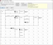
Seas L26ROY (new XM001 version) in 40 litre box with the L26 Passive radiator
SB 15CAC30-4 midrange in 5l closed box
SB 26CDC-4 tweeter
Box -
Bottom woofer box, separate mid/tweeter box so can be mechanically aligned
Sims -
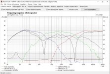
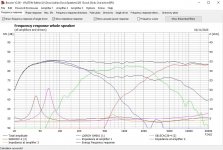
I have sim'd this in Boxsim v2.0 (results shown), PCD and Vituixcad and all pretty much give the same answers.
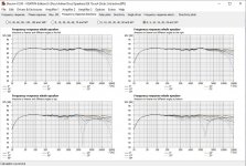
The results look pretty encouraging with a simple LR2 crossover for all drivers, LPAD for Mid/Tweeter, Inverted Mid and a couple of notches to sort out woofer and Mid breakup. I have also sim'd with active crossovers and can replicate the passive results pretty much using 275 and 2700 LR2 crossovers and a couple of parametric filters.
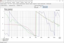
Results show a good flat frequency response on axis, a some what hard to believe phase tracking of all drivers and the only concern is the fairly flat 3ohm load. However, I will be initially using an active crossover and tri amping so should be OK.
I understand that I will need to buy the drivers, measure and re-run the sims but how close will real life be to these sims ?
So, questions, is this too good to be true as a first effort or is there stuff I should change and is there a way of increasing the impedance across the board of the passive circuit. All comment welcome as I am here to learn, please do RIA, thanks in advance.
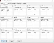
Graphs attached from Boxsim, PCD and rough design.
Been looking at a wide range of speakers and learning some of the crossover packages and seem to have stumbled on what looks like a pretty good and reasonable cost design. Please can those more intelligent and experienced than me have a look to see if I have missed anything, bearing in mind there are from manufacturers specs ?
Drivers -
Seas L26ROY (new XM001 version) in 40 litre box with the L26 Passive radiator
SB 15CAC30-4 midrange in 5l closed box
SB 26CDC-4 tweeter
Box -
Bottom woofer box, separate mid/tweeter box so can be mechanically aligned
Sims -
I have sim'd this in Boxsim v2.0 (results shown), PCD and Vituixcad and all pretty much give the same answers.
The results look pretty encouraging with a simple LR2 crossover for all drivers, LPAD for Mid/Tweeter, Inverted Mid and a couple of notches to sort out woofer and Mid breakup. I have also sim'd with active crossovers and can replicate the passive results pretty much using 275 and 2700 LR2 crossovers and a couple of parametric filters.
Results show a good flat frequency response on axis, a some what hard to believe phase tracking of all drivers and the only concern is the fairly flat 3ohm load. However, I will be initially using an active crossover and tri amping so should be OK.
I understand that I will need to buy the drivers, measure and re-run the sims but how close will real life be to these sims ?
So, questions, is this too good to be true as a first effort or is there stuff I should change and is there a way of increasing the impedance across the board of the passive circuit. All comment welcome as I am here to learn, please do RIA, thanks in advance.
Graphs attached from Boxsim, PCD and rough design.
Attachments
-
 L26ROY 15CAC4 26CDC Box.JPG32 KB · Views: 307
 -
 L26ROY 15CAC4 26CDC PCD.JPG181.4 KB · Views: 185
 -
 L26ROY 15CAC4 26CDC Xover.JPG142.1 KB · Views: 172
 -
 L26ROY 15CAC4 26CDC Phase.JPG144.9 KB · Views: 306
 -
 L26ROY 15CAC4 26CDC FreqOffAxis.JPG197.2 KB · Views: 309
 -
 L26ROY 15CAC4 26CDC FreqInv.JPG175.9 KB · Views: 301
 -
 L26ROY 15CAC4 26CDC Freq.JPG176.8 KB · Views: 302
You are right to be suspicious, it does look remarkable good. Where did the driver frequency responses come from? They look extremely smooth. Your sim is probably OK, but the driver responses are "optimistic."
Hello to UK ,
I dont see, why this driver should not be working.
Concept and Chassis look, as if they could match well.
Did you also consider the baffle step / diffraction?
Dont know, how to interpret the Boxsim-Simulation or what your simulation is based on.
Maybe you should validate with vituixCad, since it has more functions.
Your current sim looks good, but keep in mind that the actual measured driver responses will be different and the z axis needs to be measured. If you don't have measurement capability, I would suggest purchasing that first, as you sim skills seem good. Good luck with the build.
You really should be using your actual in box measurements. You don't know the measurement conditions or smoothing used with the factory ones. The sim's look great but your inbox measurements will be more accurate and more representative of what you will actually end up with.
Rob 🙂
Rob 🙂
Thanks guys, really encouraging that I have made no daft errors and this is the sort of sim result I am supposed to aim for. I have assumed that the aim is flat(ish) on axis frequency response, flat(ish) impedance response and above 3ohms, big dips In on axis frequency when mid is inverted, and co-incident phase for at least one octave above and below crossover points. Am I on the right path.
For Z I plan on putting all three drivers in separate boxes so I can physically align them.
I have a Behringer ECM8000 mic and UMC202HD interface. I know the 8000 is not calibrated but there are generic calibration to get me going plus I may be able to do my own calibration against a calibrated mic.
You are definitely on a path toward success. Your sims show this set of drivers are well matched, and a good crossover filter is feasible and low risk. I recommend the next steps are to acquire the drivers, build the boxes, measure, redesign crossover (it might need just a small adjustment or a substantial change), finish, enjoy...
To increase the overall impedance of the system, you could do 2 things... (1) switch from the 4 ohm SB15CAC30 to the 8 ohm version (2) change the tweeter resistor network - you have 5.6 ohm in parallel with the tweeter and this probably brings the impedance down in the upper regions.
So it was not clear to me if this is going to be an active speaker or passive?
...is there a way of increasing the impedance across the board of the passive circuit
To increase the overall impedance of the system, you could do 2 things... (1) switch from the 4 ohm SB15CAC30 to the 8 ohm version (2) change the tweeter resistor network - you have 5.6 ohm in parallel with the tweeter and this probably brings the impedance down in the upper regions.
So it was not clear to me if this is going to be an active speaker or passive?
@hifijim - I have a minidsp system with 6 channel amp that I will use to get an active system going first but would like to move to a passive at some stage.
Dsp is - Minidsp Nanodigi plus 4x Khadas Toneboard plus Rotel RMB1066
DSP Crossover project
Dsp is - Minidsp Nanodigi plus 4x Khadas Toneboard plus Rotel RMB1066
DSP Crossover project
@wolf_teeth, that was my worry, all three drivers are nominally 4 ohms, what would you suggest I change to rectify this?
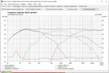
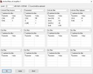
Just to complete the picture here are the settings and graphs for the active solution. Pretty much the same but not quite as good phase alignment in the woofer/mid but I am sure a few tweaks could solve this.
Attachments
-
 L26ROY 15CAC4 26CDC Freq act.JPG178.5 KB · Views: 108
 -
 L26ROY 15CAC4 26CDC Phase act.JPG145.9 KB · Views: 109
 -
 L26ROY 15CAC4 26CDC FreqOffAxis Act.JPG194.5 KB · Views: 104
 -
 L26ROY Act Filt.JPG75.7 KB · Views: 105
 -
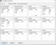 SB15CAC30-4 Act Filt.JPG79.9 KB · Views: 96
 -
 SB26CDC-6 Act Filt.JPG72.3 KB · Views: 52
I'm not sure if you have bought these drivers yet, but IMO, 4 ohm drivers are getting into a World of Hurt for a 3 way.
This is the sort of thing that works well:
SEAS-3-Way-Classic
It's terribly difficult to avoid low impedance in a 3 way at the best of times.
This is the sort of thing that works well:
SEAS-3-Way-Classic
It's terribly difficult to avoid low impedance in a 3 way at the best of times.
- Home
- Loudspeakers
- Multi-Way
- Too good to be true - Crossover Check please