Hi
I've just built a Bass guitar preamp, but am unable to get the bypassable EQ section working (attached schematic). - the bass and treble do nothing, and the mid with the selectable frequency act more like a volume control across all frequencies. With the EQ bypassed the preamp works very well. I've checked the construction, PCB layout, values and tried several op amps with no success and must now accept that I've reached my level of incompitance - Can anyone suggest what I should be looking at
Thanks
Richard
Attachments
Hi jandr49,
Some areas to explore:
Check the bias for IC1a and IC1b. Pins 1 and 7 should read 0V with respect to ground. IC1b derives its DC bias via R17 and P3, the bass control. If the bias is satisfactory, with S5 set to EQ, if you take the output temporarily from pin 1 of IC1, this should be at the same volume level as point (B) in the circuit.
Double-check the values of C10, C12 and C13. Ensure that you haven't accidentally inserted a capacitor in series with the wiper of P3 as this would upset the bias of IC1b.
Hope that helps.
Regards,
Steve
Being a new constructor, I suspect u have overheated and blown the IC or it is a dry solder problem.
Try replacing the IC.
Gajanan Phadte
Try replacing the IC.
Gajanan Phadte
Thanks for the suggestion but I've already replaced the IC (plugs into a socket) and resoldered all other relevant components with no success.
That's weird. Sounds like the opamps are working OK, else you'd get nothing out.the bass and treble do nothing, and the mid with the selectable frequency act more like a volume control ...
Maybe the pots are wired up wrong?
Are you sure the capacitors are all the correct values? (Beware e.g. the difference between 22pF, 22nF and 22 uF)
Some pictures might help e.g. PCB layout or photos of actual construction.
Cheers - Godfrey
p.s. Was this a kit or are there full plans available online somewhere?
Just asking because another member wanted to build a bass guitar amp recently and couldn't find any plans...
Last edited:
jandr49
Did you use a symmetrical power supply similar to that linked on
this page?
PSU circuit (direct link):
http://www.albertkreuzer.com/pics/el/pre/schem/psu01_sch.gif
Regards,
Steve
Did you use a symmetrical power supply similar to that linked on
this page?
PSU circuit (direct link):
http://www.albertkreuzer.com/pics/el/pre/schem/psu01_sch.gif
Regards,
Steve
Would you try to bypass IC1a and feed the output from the drain of the FET directly to the junction of R15/R18/R20 and see if the problem persists?
A Baxandall typically behaves like this when there is no amplification happening. The audio signal will still flow through the various resistors to the output almost unimpeded, and if the following stage has sufficiently high impedance it will not even result in a drop in output.
I would check the supplies, all the connections and the chips again.
Hi - Thanks for all the input its given me something to work on and check - the power supply is a +15/-15v symetrical and from the Albert Kreuzer website as were the PCB designs and component layout. I've checked the bias on IC1a and b - pin 1 is at 0v but pin 7 varies between 16mv and 1.3v depending on the position of P4 - I've removed the switched mid range select switch and capacitors to simplyfy it, and replaced them with the original 4n7 and 22n capacitors but it made no difference. The signal level at pin 1 is also identical to point B. I've visually checked all the resistor and capacitor values and the board layout and can't see anything wrong but perhaps I've looked at it too long and am seeing what I expect to see. I've attached the pc/component layout and will try to arrange a picture of the construction
Thanks
Richard
Thanks
Richard
Attachments
Hi jandr49,
IC1a seems to be working normally from your tests.
I am baffled as to why P4 would have any effect on the DC offset at IC1b pin 7. P4 is the mid-range control and is capacitively coupled via C12. Are you sure you didn't mean P3? If you meant P4, check that C12 isn't "leaky" - try replacing it.
Something else to try: Disconnect the wiper (centre) pins of P4 and P5 then see what effect P3 has on the sound.
Regards,
Steve
I used a new capacitor for c12 when I removed the mid frequency switch so believe that to be ok - Ive just disconected the wipers on P4 and P5 and p3 still has no effect - but the signal level at pin 7 is stable at 50% of the signal level at pin 1. Pin 2 and 3 are at 0v as is pin 5 - Pin 6 is at 6 mv - pin 4 has -15v and pin 8 has +15v
Regards
Richard
Regards
Richard
To check the gain of IC1b, leave P4 and P5 wipers still disconnected. Temporarily disconnect or remove C10 (56nF). Set the wiper of P3 midway. Now if you feed audio into the 'low' or 'high' inputs, set S5 to EQ, close S2 and listen to the outputs on pins 1 and 7 of IC1, they should be at the same level and give a flat audio response. If this is not the case, there could be something wrong with the resistor values of R15/R16.
Adjusting P3 should control the volume:
Between points B and C, P3 will vary the gain between 0.09 and 11.
Regards,
Steve
Adjusting P3 should control the volume:
Between points B and C, P3 will vary the gain between 0.09 and 11.
Regards,
Steve
This 3 band corrector is the most displayed on the internet..
As i told you, P5 must be 470k or 500k...
R15/16 have the good value.
R18/R19 should rather be 3.3k...
For the midrange, set C11 to 4.7nF and C12 to 22nF
as displayed on the schematic...
If those value don t work, then there s a flaw either on the pcb
or on the connections to the pots...
T
As i told you, P5 must be 470k or 500k...
R15/16 have the good value.
R18/R19 should rather be 3.3k...
For the midrange, set C11 to 4.7nF and C12 to 22nF
as displayed on the schematic...
If those value don t work, then there s a flaw either on the pcb
or on the connections to the pots...
T
Hi Wahab
Thanks for the advise and I'll try those values when I can obtain them - What center frequencies will that give me for the mid and treble controls as this is for a bass guitar and they need to be 1k and 2k respectivly.
I've done what you suggested Steve, and I seem to have a problem as there is no change - the output of pin 7 is still approx 50% of pin 1 and P3 has no effect on volume - I've swaped IC1 with IC2 - the tuner and clip threshold (IC2) still work and there is no change to the operation of IC1 - R15 and 16 both measure at 10K and I still cant identify a problem with the board or construction - I think I'm too close to it at moment so will probably put it away for a few days and perhaps the error will be obvious to me in a few days time - thanks everyone for the help
Regards
Richard
Richard,
With P4 and P5 wipers disconnected, C10 disconnected and P3 set to mid-point, the gain of IC1b stage is determined by:
(R16 + (P3/2)) / (R15 + (P3/2))
As R16 = R15, the gain should be unity (1).
When P3 wiper is nearest R15, the gain is:
(P3 +R16) / R15 = 110K/10K = 11
When P3 wiper is nearest R16, the gain is:
R16 / (R15 + P3) = 10K/110K = 0.09
Check for shorts and/or breaks on the board around IC1 pins 5-6-7 and its resistors, the correct resistor values and whether P3 is actually faulty. You are so close at this point!
Regards,
Steve
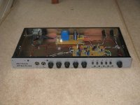
Now working perfectly - found a crack in the track feeding R15 - thanks for leading me there Steve, and everybody else who helped - I've learnt a vast amount from this build
Regards
Richard
Regards
Richard
Attachments
Last edited:
Pleased to hear you located the problem Richard 🙂
A good-looking result too!
Now you can check the controls' centre frequencies.
Regards,
Steve
A good-looking result too!
Now you can check the controls' centre frequencies.
Regards,
Steve
- Status
- Not open for further replies.
- Home
- Amplifiers
- Solid State
- Tone control not working