Hi all,
Has anyone come across a good simple design for a DIY arm lift?
or alternatively a source for buying them new?
I could do with one for a new unipivot I made and although I've looked at a few vintage decks for scavenging they all are automatic lifts.
Fran
Has anyone come across a good simple design for a DIY arm lift?
or alternatively a source for buying them new?
I could do with one for a new unipivot I made and although I've looked at a few vintage decks for scavenging they all are automatic lifts.
Fran
for a mechanism...
something like a bicycle seat post "quick release" could be ok. Basically a cam in a end with a handle.
something like a bicycle seat post "quick release" could be ok. Basically a cam in a end with a handle.
Can be bought new from Jelco in Japan, their model JL45. If you start a GB I'm in for at least two.
Jelco site (scroll for JL45)
Jelco site (scroll for JL45)
Whatever you do you might keep in mind that the viscous effect is obtained with some very thick silicon oil.
Keeping in mind that 90W differential oil is way less than 100 rating.
The silicon viscous fluid comes in ratings of 30,000, 50,000 and on up to 500K.
It is used in the differentials of hobby cars. 50K is probably what you would want to try first. Mark
Keeping in mind that 90W differential oil is way less than 100 rating.
The silicon viscous fluid comes in ratings of 30,000, 50,000 and on up to 500K.
It is used in the differentials of hobby cars. 50K is probably what you would want to try first. Mark
hailteflon said:
Keeping in mind that 90W differential oil is way less than 100 rating.
The silicon viscous fluid comes in ratings of 30,000, 50,000 and on up to 500K.
You appear to be confusing SAE oil ratings ( eg 90W) with actual viscosity measurements in centiPoise (eg 30,000).
The two are only distantly related as seen here:
Roymech on Viscosity
No, I found some spec sheets for some gear lube and the cp number is surprisingly low. I may have been higher than 100, but I am not confusing the two rating systems.
The following is from a gear lube spec sheet. This is one of about twenty lube pages that I stored. I don't know if the cSt is the same as the cp. This is 140W gear oil.
Appearance Light Straw Transparent Fluid
Viscosity, cSt @ 100°C 55.41 77.35
Viscosity, cSt @ 40°C 697.54 1079.19
Viscosity Index 140 145
If I find a spec that says "cp" then I will post it. I tried STP and it did nothing. I tried silicon grease and it did nothing.
I tried to align the chart, but the preview messes it up again, sorry.
I've sent an email to Jelco to see how much they cost etc. But at this moment something in the DIY route is preferable. The damping isn't that critical to me, just a lift/lower is all thats required...
Fran
Fran
You may find that viscous damping is more important than you thought.
Mr. Kelly's post has raised a good question. What rating system is used? For those who may be interested in the future I will post the results if I can find an MSDS on traxxas diff lube 30W product number TRA5136.
The following is what I have found so far.
The viscosity of water at room temperature is approximately 1 cP
cp (centipoise) is the dynamic viscosity and cst (centistokes) is the kinematic
viscosity. I was unable to find a conversion factor because the units are different.
“Valvoline Gear Lube passed the test at 130,000 cP, “ said of 90W gear oil. So, the weight of this silicone oil isn’t in cp. The bottle says “30K weight.”
Traxxas has one of those ultra-worthless websites that will not readily respond to the description, labels, or part numbers of its own products. If I figure out what 30K weight means on the bottle I will post it.
To convert between dynamic and kinematic viscosity you simply divide by the density. Read the reference I posted above (Roymech).
I believe that the standard "weights" of silicone oil in the US are in cS, that's certainly how Dow Corning specify theirs. Since silicone oil has a density very close to 1 g/cc, I don't think there's a big difference between cS and cP for these fluids.
I believe that the standard "weights" of silicone oil in the US are in cS, that's certainly how Dow Corning specify theirs. Since silicone oil has a density very close to 1 g/cc, I don't think there's a big difference between cS and cP for these fluids.
Divide by the density. Sounds easy enough.
The following is about the super-thick silicone fluids.
100,000 cSt dimethyl silicone fluid emulsion
Zander Colloids website
This is evidently where I got the comparison to gear lube.
So, 90W gear oil is about 1000cst at room temp.
This silicone fluid is some thick stuff.
The following is about the super-thick silicone fluids.
100,000 cSt dimethyl silicone fluid emulsion
Zander Colloids website
This is evidently where I got the comparison to gear lube.
So, 90W gear oil is about 1000cst at room temp.
This silicone fluid is some thick stuff.
At the risk of stopping the discussion on viscosity, I'll point out that it's harder to make a cueing device than the pick-up arm it's to be used with!
Maybe not. This fluid can turn most any mechanism into viscous damping.
If you built a lever in any sort of bushing underneath the tonearm it would be viscous with the higher viscosity fluids. They are so thick that they don't run.
Sort of a U-shaped lever with one leg under the tonearm and the other to move it with. A U-shape that has been bent such that the two legs are about 45 degrees out of phase.
The problem with no damping, aside from the frustration of trying to control it, is that it is very tough on cantilevers and woofers if dropped.
Look at some of the cheap BSR changers. You may be able to strip most of it out and convert it.
Post a picture of what you build.
Good Luck, Mark
At the risk of stopping the discussion on viscosity, I'll point out that it's harder to make a cueing device than the pick-up arm it's to be used with!
Your dead right there! I've been thinking and thinking but haven't solved it yet. Heads need to be knocked together on this one.
On the damping: I wouldn't mind having to lower the lever by hand to drop the needle gently, but of course damping would be nicer to use. Will need to think about this one. Is there nothing available off the shelf that could be modified to suit - a piston type assembly?
Fran
I'll make this quick, need to shut down this 'puter because of lightning.
If you are in the USA, can't see your profile from here, use Ace hardware.
K&S tubing and brass rods. Look at the boxes of hardware. Nylon bushings etc.
Hobby shops, lot of neat stuff for building airplanes.
Back later. Mark
If you are in the USA, can't see your profile from here, use Ace hardware.
K&S tubing and brass rods. Look at the boxes of hardware. Nylon bushings etc.
Hobby shops, lot of neat stuff for building airplanes.
Back later. Mark
I'm just back in form the workshop where I've failed pretty miserably in making one! I have a nice piece of shaft, a sleeve with a smooth fit (alittle grease would give the damping easily) and a curved piece that the arm actually sits on. I just couldn't get something that would work as a lever and mech to rise and fall and stay up when its up.
This is a PITA.
Fran
This is a PITA.
Fran
Have a look at some old cassette decks: the load/eject mechs are often damped using a dashpot which could easily be removed and reused.
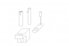
Pick-up lift.
Hi,
A simple but effective pickup lift can be made out of readily available materials, for not much cost, and with minimal tools like a miniature hacksaw, file, drill etc.
If I can show an attachment (it didn't when I checked "Preview Reply"!), this should become clear, and the hardest part for anyone without a good workshop will probably be drilling the base where 2 holes are needed at right angles to each other. The materials can be softer metals like aluminium or even acrylic etc., which will make any drilling sawing and filing less onerous, and will be quite adequate for this purpose. Incidentally, knitting-needles, which are available in plastic and highly-polished alloy in all different diameters, are very useful for making thinner rods or bars, and are also easy to obtain and inexpensive.
The main parts are the slotted tube which needs to be chosen to suit a piece of round bar as a close 'slip fit', and the inner bar which has the rod inserted at right angles to form the pick-up arm support. The cam is made also from (the same?) round bar, with a part of it removed by filing, and this is inserted from the back of the base-block, with a couple of small pins at each side of the base being fitted in the round bar to locate this cam, to prevent lateral movement. The second pin is inserted after the cam is located in the base, and if provision is made for a washer at both faces of the base, this will prevent any sticking or scraping when the lift is in use.
Then the tube is glued (if the fit is not tight enough without) into the vertical hole in the base, with the slot aligned suitably for the arm position, and the inner rod is slid down so that the arm-lifting peg is within the slot. When rotating the cam via the handle, the inner rod and arm-lifting peg will then move up and down, as will the arm if this is positioned appropriately.
No dimensions are critical, and it is best to draw the various parts out to scale first to establish the required lifting-action of the cam, and the positioning of the entire lift compared with the arm and the base-board of the turntable, to ensure that it all works as intended.
I hope this may help, and can anyone who might be interested tell me how to convert a bitmap (bmp) image into something suitable to attach here. This appears to be the problem with my attachment which I drew in Paint and cannot be shown in this format according to the Forum messages.
I haven't thought this through, but what about using a motorized system to control lift speed? One could start out with a servo used for radio control models. You wouldn't need to deal with the viscosity stuff.
If you are going to use the cylinder approach the 50K fluid will be too thick unless the tolerances are very sloppy.
A close tolerance cylinder may be very hard to calibrate for drop time.
As I recall, many of the vicous cueing devices are more of a paddle moving through a puddle of the viscous silicone. Mark
A close tolerance cylinder may be very hard to calibrate for drop time.
As I recall, many of the vicous cueing devices are more of a paddle moving through a puddle of the viscous silicone. Mark
- Status
- Not open for further replies.
- Home
- Source & Line
- Analogue Source
- tone arm lift